
RS-485 Wiring for Modbus RTU: Common Field Problems
A Modbus RTU configuration can be correct in software and still fail because the RS-485 physical layer is poor. Wiring problems are especially likely when communication works on a short bench cable but becomes intermittent after the real field network is connected.
The useful approach is not to apply one universal RS-485 recipe. Check the topology, termination, reference and cable arrangement against the actual transceivers and device manuals.
A and B labels are not universal polarity definitions
“Swap A and B” is common troubleshooting advice, but it is too simplistic as a design rule. Manufacturers do not use A/B labels consistently enough to assume that terminal A on one product always connects to terminal A on another.
Compare the electrical terminal definitions in both manuals. Some manufacturers also label the pair as D+ / D-, + / - or use other conventions. The important point is the actual signal polarity expected by the transceivers, not the letters printed beside the connector.
If a two-device link has never communicated, checking the pair against both manuals is sensible. If the network previously worked and then became unstable, randomly swapping conductors is less useful than looking for what changed.
Keep the network close to a trunk topology
RS-485 is normally easiest to manage as one main trunk with devices connected along the line. Long branches and star wiring create additional discontinuities where signals can reflect.
Short stubs are often unavoidable in real panels, but their acceptable length depends on baud rate, cable and the transceivers. There is no useful universal stub-length number that applies to every Modbus installation.
When a bus works with two devices but becomes unreliable after more devices are added, inspect how the new devices were physically connected before changing protocol settings.
Termination belongs to the transmission line, not every device
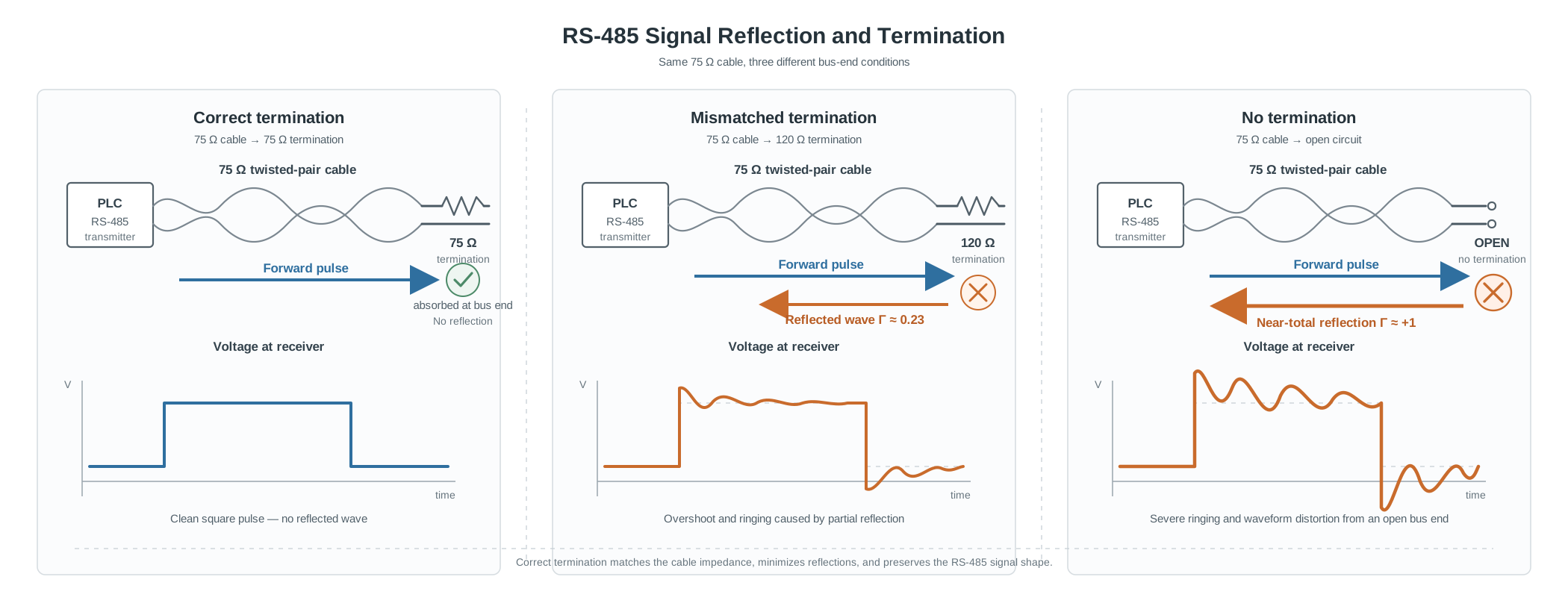
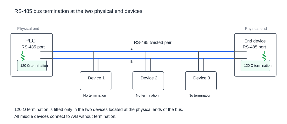
Termination is used to reduce reflections by matching the transmission line where appropriate. In a typical RS-485 trunk using cable with a characteristic impedance around 120 ohms, a similar termination value at the physical ends is common practice. The actual equipment instructions still control the installation.
Common mistakes include:
- no termination on a long or electrically difficult trunk when the equipment requires it
- termination enabled at several intermediate devices
- both physical ends left unterminated while an intermediate device is terminated
- assuming the same resistor value is correct for every cable and product
Do not add resistors until the existing termination switches or jumpers are known. Many devices already include selectable termination internally.
Reference conductor, shield and grounding need a deliberate design
RS-485 signalling is differential, but the transceivers still have a permitted common-mode voltage range. Some installations therefore require a signal reference conductor between devices. Whether and how that conductor is connected is device- and project-specific.
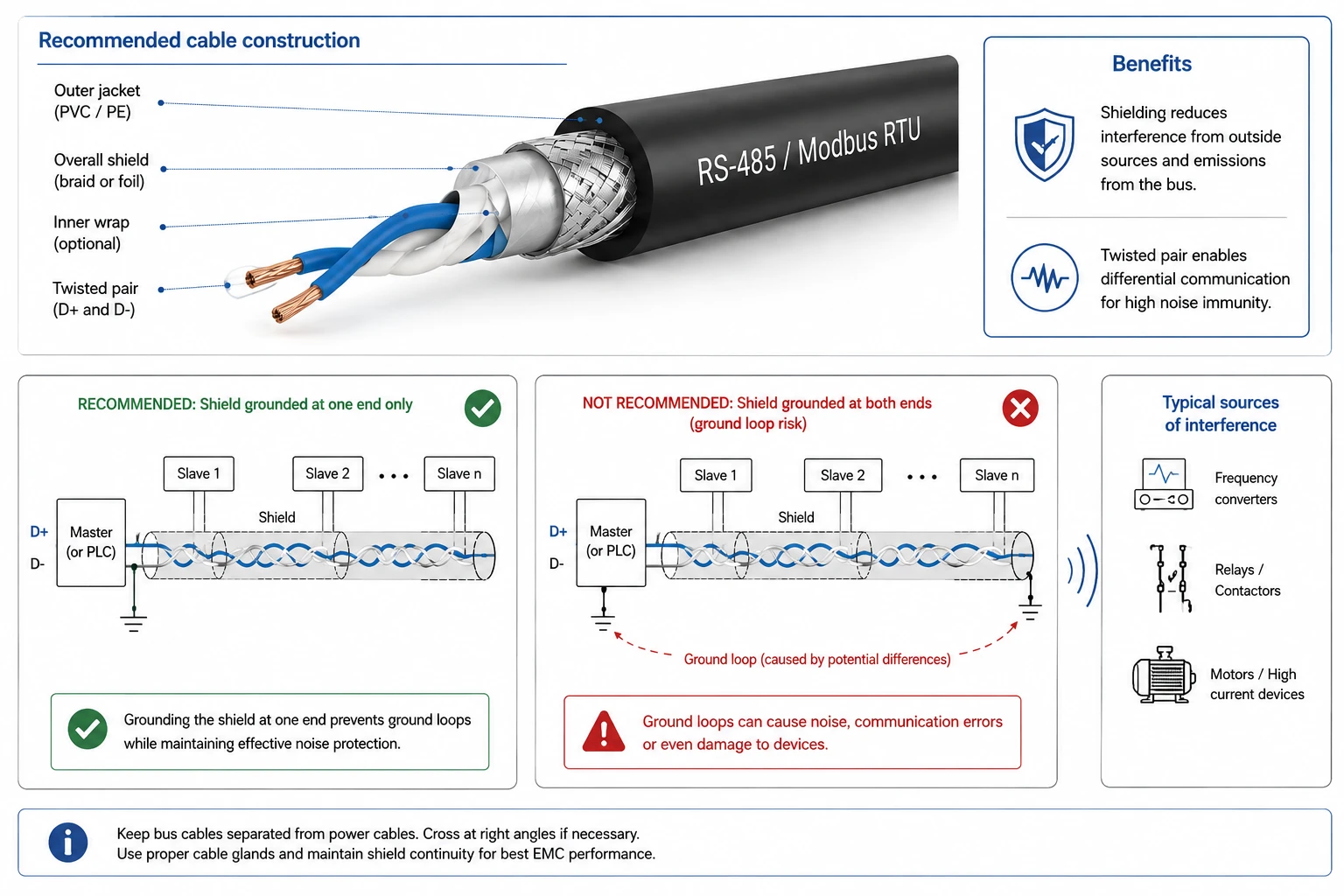
The same applies to cable shields and grounding. A statement such as “always ground the shield at one end” is too broad for every building automation installation. Follow the electrical design and manufacturer instructions, especially when devices are supplied from different panels or earthing systems.
If communication changes when a laptop, USB adapter or another earthed device is connected, investigate reference and grounding conditions rather than treating the adapter as a mysterious protocol fault.
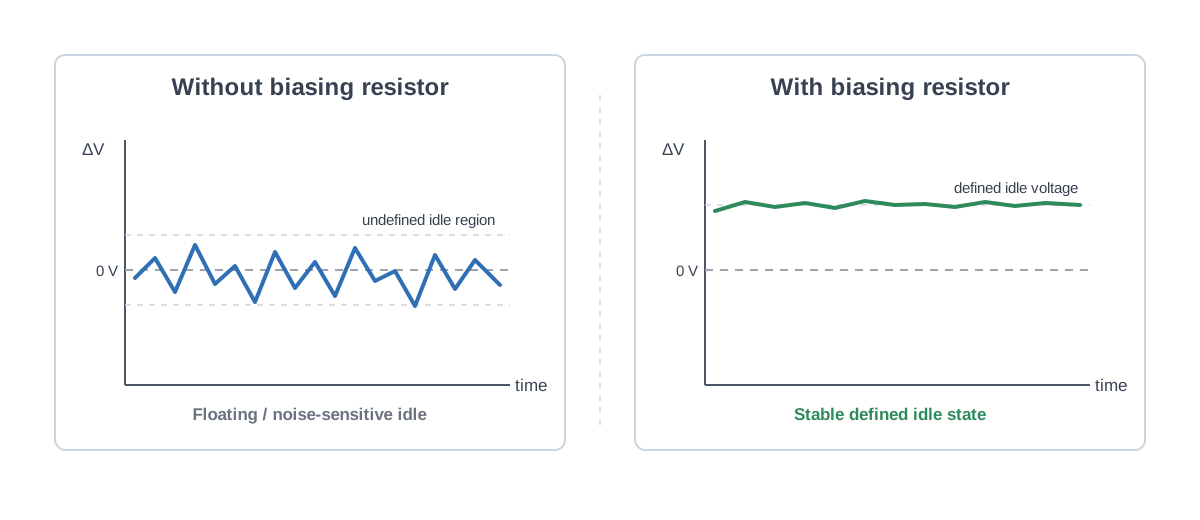
Biasing is another separate part of the physical layer. Some RS-485 networks require a defined idle state, but whether bias resistors are needed and where they are implemented depends on the connected equipment. Before adding external biasing, check whether it is already provided by the client, gateway or another device.
Cable routing and electrical noise can make a marginal bus fail
A clean office bench is not the same environment as a plant room or electrical cabinet. VFD motor cables, contactors, relays and other switching equipment can increase electromagnetic interference.
Look for correlations. Does the error rate increase when a fan drive starts? Does communication fail only when a contactor switches? Does moving the RS-485 cable away from power conductors improve the result?
Those observations are more useful than replacing software settings randomly.
Loose connections create intermittent faults that look like software bugs
A loose terminal can produce exactly the kind of problem that consumes hours of debugging: communication works during commissioning, fails later, returns after a cabinet is opened and disappears again after vibration or temperature changes.
Inspect:
- terminal tightness
- damaged or poorly stripped conductors
- shield strands touching signal terminals
- connectors under mechanical stress
- field joints hidden outside the controller cabinet
A continuity check with the system powered down can be useful, but remember that simple continuity does not prove good signal integrity under operation.
Duplicate Modbus addresses are not a wiring fault, but appear after network expansion
When another server is added to an existing trunk, confirm that its Modbus address is unique before blaming the cabling. Two devices replying to the same request can corrupt responses or create behaviour that changes depending on timing.
This is a useful distinction: the physical installation may be perfectly good while the network configuration is not.
Do not rely on generic maximum distance or device-count numbers
The usable RS-485 segment length and number of devices depend on cable characteristics, baud rate, transceiver loading, termination, topology, EMC conditions and the device specifications. Modern transceivers also differ significantly from older assumptions about unit loads.
Use the actual device documentation when there is a stated node, cable or baud-rate limit. Generic rules are useful for understanding the mechanism, not for overriding product specifications.
A practical field check
When an RS-485 Modbus trunk is unstable:
- Record the symptom before changing anything.
- Verify serial settings and unique Modbus addresses.
- Compare A/B or +/- terminal definitions from both device manuals.
- Sketch the real cable route and identify every branch.
- Identify where termination is actually enabled.
- Check reference, shield and grounding arrangements.
- Inspect terminals and field joints.
- Look for correlation with drives, contactors and other noise sources.
- Reduce the network temporarily to a short known-good segment if needed.
- Reconnect sections methodically until the fault returns.
If the physical layer looks healthy but no response is received, return to the Modbus RTU troubleshooting sequence.