
Modbus Addressing: 40001, 0-Based and 1-Based
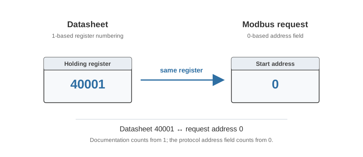
Few Modbus details create as much unnecessary commissioning work as register numbering. A manufacturer may write 40001, one PLC may ask for 0, another tool may display 1, and all three can refer to the same holding-register location.
The important point is that these are representations of an address, not three different registers.
The protocol request uses an address field
At the Modbus protocol level, the starting address in a register request is a 16-bit value. For the first register in a data block, that protocol address is commonly 0.
For example, a Read Holding Registers request for the first holding register can contain:
Starting address = 0x0000
Quantity = 1
The request does not transmit the decimal number 40001 as the starting address.
Why 40001 exists
The 4xxxx notation is a historical human-facing reference convention. It indicates that the value belongs to the Holding Register data model and gives it a register reference number.
In the common convention:
| Same logical location | Representation |
|---|---|
| Protocol offset | 0 |
| One-based register number | 1 |
| Holding-register reference | 40001 |
The next location is typically shown as:
| Same logical location | Representation |
|---|---|
| Protocol offset | 1 |
| One-based register number | 2 |
| Holding-register reference | 40002 |
This is why “subtract one” sometimes fixes a Modbus integration. It is not a universal repair method. It works only when the documentation and client are using different bases for the same register block.
The same number can mean different things in different tools
A field labelled Address is not enough information.
One client may expect the raw protocol offset:
0
Another may present one-based register numbers:
1
A third may allow a full reference:
40001
Before changing the number, find out what the client expects. Good software often states this explicitly in the UI or manual. If it does not, inspect the actual request frame or test against a register whose value is already known.
A successful read can still be one register wrong
Addressing mistakes are more dangerous when the neighbouring register also contains a valid value.
Suppose the manual intends:
| Protocol offset | Description |
|---|---|
| 100 | Supply air temperature |
| 101 | Supply air setpoint |
If the integrator interprets the documented address as one-based when it is actually zero-based, the request may read offset 101. The device replies normally, but the returned number belongs to the setpoint rather than the measurement.
A complete timeout is obvious. A plausible value from the wrong register can survive commissioning.
Register type still matters
A Modbus address is meaningful together with the data model or function code. Protocol offset 0 in Holding Registers is not the same data point as protocol offset 0 in Input Registers.
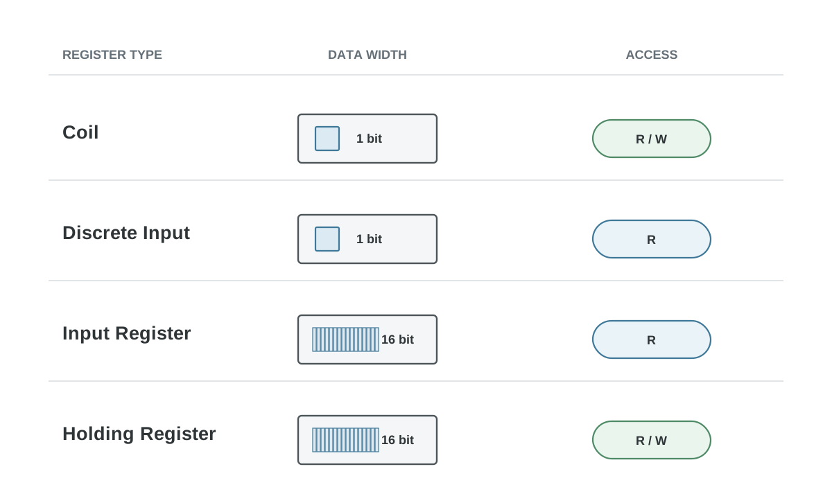
Typical reads are:
| Data model | Common read function |
|---|---|
| Coils | 01 |
| Discrete Inputs | 02 |
| Holding Registers | 03 |
| Input Registers | 04 |
Therefore a register map should never provide only a bare number when the register type is not otherwise obvious.
How I would document addresses in a new device
For technical documentation, I prefer making the protocol offset explicit and adding the human-facing reference only when it helps the intended audience.
For example:
| Protocol offset | Reference | FC | Description |
|---|---|---|---|
| 0 | 40001 | 03 | Room temperature |
| 1 | 40002 | 03 | CO2 concentration |
| 2 | 40003 | 03 | Relative humidity |
Then add one sentence near the table:
Addresses in this document are zero-based Modbus protocol offsets. Offset 0 corresponds to holding-register reference 40001.
If the product documentation instead uses one-based register numbers, that is also workable. The important requirement is that the convention is stated explicitly and used consistently in the table, examples and screenshots.
Do not mix conventions inside one manual
A common documentation failure is to show 40001 in the register table, 0 in a software screenshot and 1 in a commissioning example without explaining that they refer to the same location.
The firmware developer may understand the relationship immediately. The customer sees three conflicting addresses.
Choose one primary representation. If another representation is useful, label it every time as protocol offset, one-based register number or 4xxxx reference instead of calling all three simply “address”.
Quick check when you suspect an offset error
- Identify the data model and function code.
- Find the first known register in the manufacturer’s table.
- Determine whether the table uses protocol offsets, one-based numbers or 4xxxx references.
- Determine what your Modbus client expects in its address field.
- Decode one actual request if there is still uncertainty.
- Confirm the result against a known physical value or device state.
Do not keep trying nearby addresses until one number looks believable. That can hide a systematic off-by-one error.
For raw frame inspection, use the online Modbus decoder. For broader protocol fundamentals, see the Modbus RTU and TCP guide.