
How to Test a Modbus Device Before Release
A Modbus interface is not ready for release just because one test client can read one register. The customer receives a device, a register map and a set of communication settings. Those three things need to work together under normal operation, invalid requests, power cycles and real fault conditions.
The strongest test is performed from the customer’s side. Use the released documentation, a normal Modbus client and as little private firmware knowledge as possible. Every undocumented assumption discovered during the test is useful because it can still be fixed before customers build integrations around it.
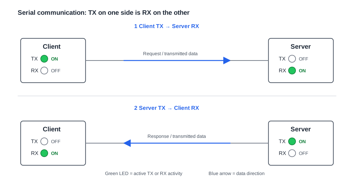
Start from factory defaults
Begin with the product exactly as a new customer receives it.
Record and test:
- default Modbus address
- baud rate
- parity
- stop bits
- supported function codes
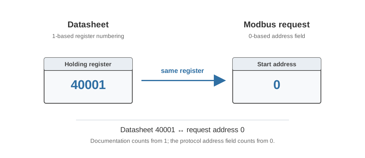
- addressing convention used in the manual
If the manual advertises several baud rates or parity modes, test the combinations the manufacturer claims to support. A setting that appears in the UI but has never been verified is still part of the product surface once customers can select it.
It is better to support a smaller set of communication modes deliberately than to expose every capability of the UART and discover compatibility problems in the field.
Test communication-setting changes as a complete workflow
Changing an address, baud rate or parity through Modbus is unusual because the setting can alter the channel currently being used to perform the write.
The documentation should answer when the new setting becomes active. It may happen after the response, after a delay, after a separate save command or after a restart. The test must follow that documented behaviour.
A useful test sequence is:
- Connect using factory settings.
- Read the current communication configuration.
- Write the new address or serial setting.
- Confirm the expected response using the old settings.
- Activate the change as documented.
- Reconnect using the new settings.
- Read normal process data.
- Power-cycle the device.
- Confirm that the setting persists if it is supposed to.
- Restore the factory configuration.
Repeat this for every communication mode that is part of the specification.
Verify the register map literally
For every public value, check that the released document matches the device:
- protocol address
- register type and function code
- data type and signedness
- number of registers
- scale and engineering unit
- valid range
- resolution
- read/write access
- default value
- byte or word order where relevant
- dependencies on other settings
- persistence where relevant
Do not verify the map against an internal spreadsheet that contains corrections unavailable to customers. The released documentation is part of the interface.
A useful review method is to give the manual and device to an engineer who did not write the firmware. If the engineer has to ask whether address 1 means protocol offset 0, what “Holiday” actually does or which parity mode really works, the review has found something worth fixing.
Test writable values beyond the normal case
Writable registers need more testing than a read-only measurement because the request changes device state.
For each writable value, test:
- minimum valid value
- maximum valid value
- a value just below the range
- a value just above the range
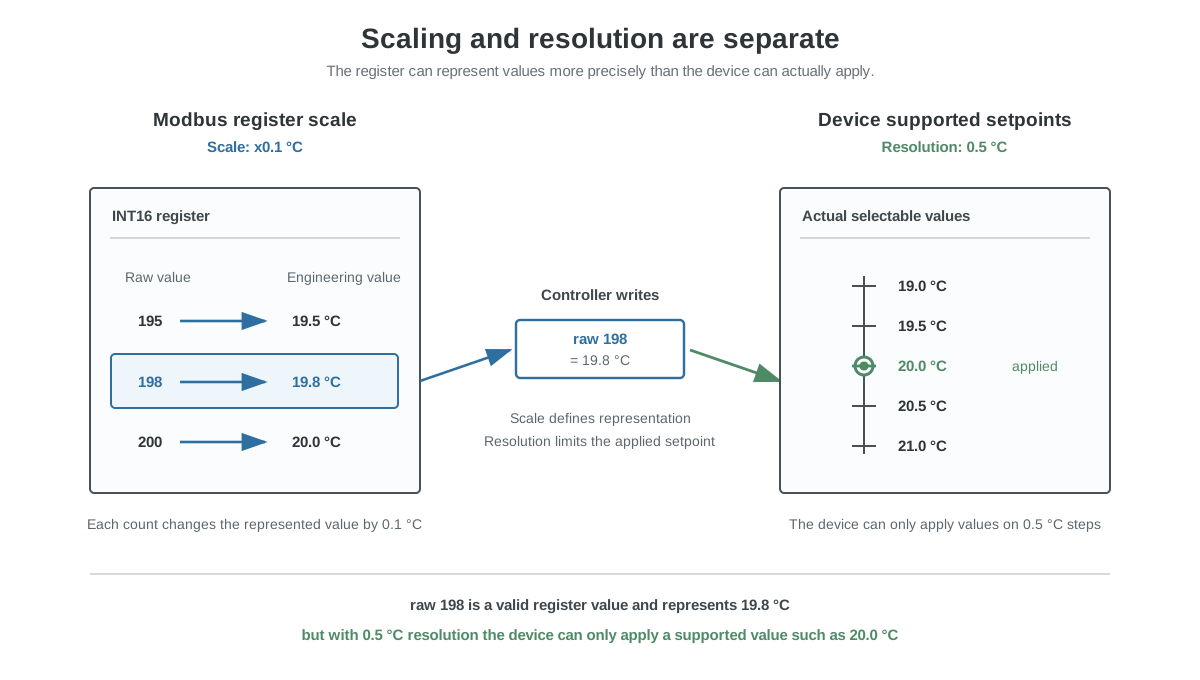
- a value that does not align with the actual resolution
- repeated writes of the same value
- immediate readback
- power-cycle behaviour
- side effects on related registers or control logic
The product team should decide whether invalid values are rejected, clamped or normalized. That behaviour should be documented rather than left to accidental type conversions in firmware.
Resolution and readback can create a repeated-write loop
Consider a setpoint represented in 0.1 °C counts while the device supports only 0.5 °C steps. The PLC writes raw value 198. The device normalizes it to 200 and returns 200 on the next read.
If the PLC assumes that any readback different from 198 means the write failed, it can write 198 again indefinitely. If the parameter is stored in EEPROM, this interface mismatch can become a hardware-wear problem even though every Modbus request and response is valid.
The test should therefore verify the effective stored value, the documented resolution and whether the firmware avoids unnecessary physical nonvolatile-memory writes when the effective value has not changed.
Test invalid and unsupported requests
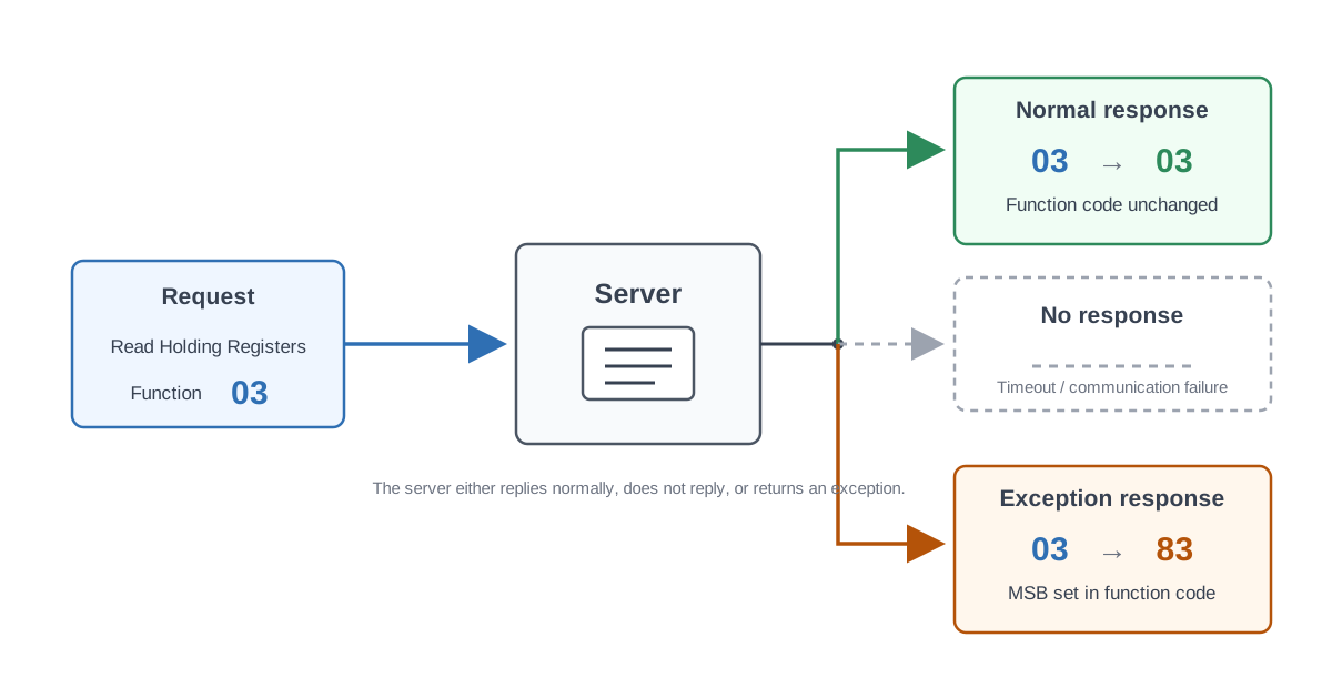
Do not test only the happy path. A public Modbus server will eventually receive requests that are unsupported, badly configured or simply wrong.
Test at least:
- first valid address
- last valid address
- address immediately before and after a valid range
- block read across a reserved or unsupported gap
- request that starts valid and ends outside the supported range
- unsupported function code
- write to a read-only register
- write to a reserved address
- invalid enum value
- request with an unsupported quantity
The correct result depends on the protocol function and device design, but one requirement is general: the request must not destabilize the device. An unsupported read must not turn into an out-of-range memory access, resource leak or reboot.
Repeat invalid requests during a longer run. Some faults appear only after buffers, counters or resources have been mishandled many times.
Test sensor and subsystem failures physically
A valid Modbus response does not prove that the underlying measurement is valid. Disconnect the sensing element or create another safe fault condition and observe what the client actually sees.
Ask:
- Does the measurement freeze at its last valid value?
- Does it become a sentinel value?
- Does a fault bit become active?
- How quickly does the fault appear?
- Does the device keep responding to Modbus?
- What happens after the sensor recovers?
- Does the value or fault state persist through a restart?
If the interface retains the last known value, provide a separate validity or fault indication so the BMS can distinguish a stable room from a dead sensor.
Normal testing proves that the mapping works. Failure testing proves that the interface remains understandable when the product does not behave normally.
Test realistic polling and long-duration operation
A device that survives manual reads every few seconds may fail under a real BMS load. Test the normal cyclic blocks at realistic intervals and include retries, occasional invalid requests and communication interruptions.
Check for:
- increasing response times
- missed requests
- memory growth or resource leaks
- watchdog resets
- counters that overflow unexpectedly
- stale responses after timeouts
- unnecessary writes caused by cyclic commands
Do not invent a universal polling interval for every Modbus product. If the device needs a minimum inter-request delay, maximum block size or other limit, measure it, specify it and test it.
Regression-test old integrations
Once a register map has been published, it becomes a compatibility surface. A firmware update should still return the old values from the same addresses with the same type, scale, alarm bits and write behaviour unless an incompatible change has been made deliberately.
Create at least one regression test representing the previously released public interface. It can be automated or semi-automated, but it should test what an old PLC or BMS integration expects rather than only the current internal implementation.
Pre-release checklist
Before publication, verify that:
- the addressing convention is explicit
- important values can be read in sensible blocks
- every register has a defined type, scale, unit and access
- writable ranges, resolution, normalization and readback are documented
- persistent and volatile values are distinguished where relevant
- advertised communication settings have been tested
- configuration changes survive restart when specified
- measurement failures have defined behaviour and quality information
- reserved and unsupported accesses fail safely
- long-duration polling does not destabilize the device
- old integrations still work after firmware changes
- the released manual has been tested literally by someone outside the firmware team
The purpose is not to prove that the development team can make the device communicate. The purpose is to verify that a customer can integrate it correctly using the public interface alone.
For the design side of the same problem, see Designing Modbus Register Maps That Integrators Can Actually Use.