
Common Modbus RTU Problems and How to Solve Them
Most Modbus RTU faults become easier to solve when the problem is separated into layers. First determine whether a request is actually being transmitted and whether the server replies. If a reply exists, determine whether it is a normal response or a Modbus exception. Only after that should the returned register data be converted into engineering values.
This order matters because a wiring fault, an invalid request and a data-conversion error can all appear as “Modbus does not work” from the controller side, but they require different fixes.
| Symptom | Check first | Typical causes |
|---|---|---|
| No response | TX/RX activity and serial settings | Wrong device address, baud/parity mismatch, wiring, power |
| Timeout | Request, response timing and server state | Wrong address, server delay, unsupported request, physical-layer fault |
| Exception response | Function code, address and quantity | Illegal function, illegal address, invalid write |
| Valid response, wrong value | Raw registers and data interpretation | Wrong address, type, signedness, scaling, word order |
| Works in one client only | Exact requests from both clients | Address convention, function code, quantity, timing |
| Intermittent communication | RS-485 installation and polling | Topology, termination, noise, loose wiring, excessive request rate |
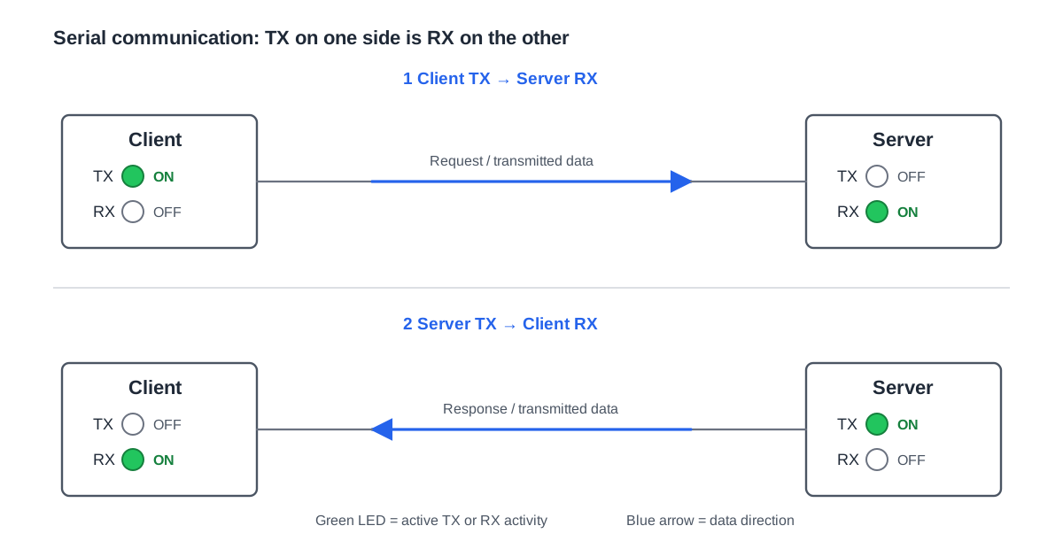
No response from the Modbus server
Start with the conditions that must exist before register addressing matters. Confirm that the device is powered, the correct serial port is used and the client is actually transmitting. If the client has TX/RX indicators or counters, check them before changing application settings.
Then compare the serial parameters on both ends. Baud rate, parity and stop-bit configuration must match the device. Verify the Modbus server address as well. A duplicate address can also cause confusing behaviour when more than one device responds on the same RS-485 network.
If the settings are correct, move to the physical layer. Check the conductors against the terminal definitions in both device manuals. Do not assume that every manufacturer uses the A and B labels with the same polarity convention. Inspect the trunk, branches, terminations, reference conductor and shield/grounding arrangement according to the actual equipment and project requirements.
A useful question is simple: does anything come back at all? If no bytes are received, changing scaling or byte order cannot solve the problem.
The device replies with a Modbus exception
An exception response is useful because it proves that the server received enough of the request to understand it. The problem has moved from basic communication toward the request itself.
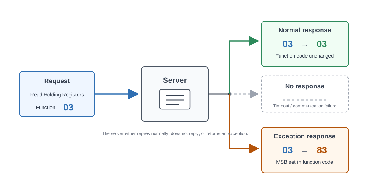
Check:
- the function code
- the protocol address
- the requested quantity
- whether the address range exists
- whether the register is writable
- whether the written value is within the device’s accepted range
For example, reading address 100 with Function Code 03 is a request for Holding Registers. Reading address 100 with Function Code 04 is a request for Input Registers. The number is the same, but the data model is different.
Also avoid assuming that a gap in a register table can always be included in a block read. Some devices return an exception when a request crosses unsupported addresses. The device documentation should state the supported blocks or limits when this matters.
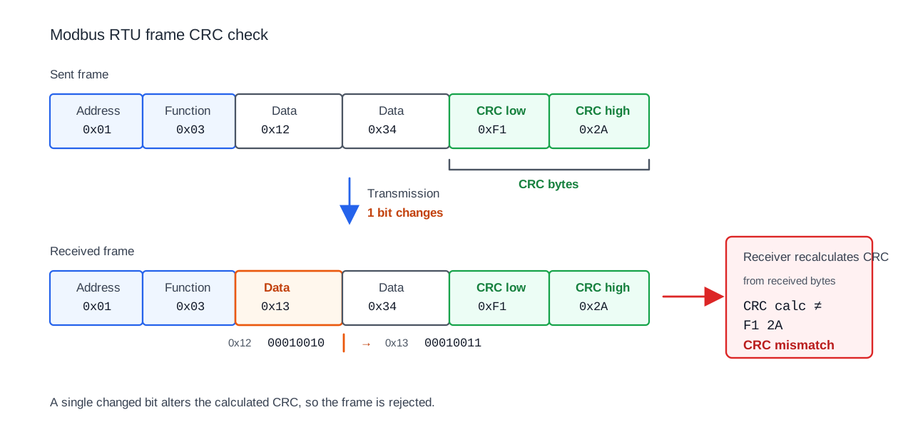
CRC errors or corrupted RTU frames
A CRC error is different from a Modbus exception. With an exception response, the server understood the request well enough to return a protocol-level error. With a CRC mismatch, the received RTU frame is not valid as received.
If CRC errors appear repeatedly, check the complete serial path: baud rate, parity, stop bits, wiring, noise, grounding/reference conditions and any converters or gateways in between. Do not recalculate the CRC and assume the field device is wrong before confirming that the captured bytes are complete and in the correct order.
Communication works, but the value is wrong
A valid response does not prove that the engineering value is correct. At this point the problem is usually no longer the RS-485 link.
Check the raw register values before applying conversions. Verify the register address, register type, data type, signedness, number of registers, byte/word order, scale, offset and unit. A negative INT16 interpreted as UINT16 can become a very large positive number. A FLOAT32 assembled from two registers in the wrong word order can also produce a valid-looking but meaningless number.
See Why Is My Modbus Value Wrong? for a step-by-step value-conversion workflow.
It works in a test tool but not in the PLC or BMS
When one client works and another does not, compare the actual requests instead of only comparing the visible configuration fields.
The difference may be:
- zero-based protocol offset versus one-based register number
- a 40001-style reference entered directly in one tool
- Function Code 03 versus 04
- different requested register counts
- different timeout or inter-request timing
- a client reading across an unsupported gap
Address conventions are especially easy to misread because the first holding-register location may be presented as protocol offset 0, register number 1 or holding-register reference 40001. These representations can refer to the same location, but the client software may expect only one of them.
See Modbus Addressing: 40001, 0-Based and 1-Based.
Communication is intermittent
Intermittent faults deserve a different approach from a complete no-response condition. A bus that works for minutes and then fails already tells you that the basic address and serial configuration may be correct.
Check whether the failure correlates with:
- another device being connected
- a VFD, contactor or other noisy load operating
- longer cable sections or branches
- cabinet doors or field wiring being moved
- a higher polling rate
- retries beginning after one slow response
- loose or oxidized terminals
On RS-485, verify the topology and termination against the equipment requirements. Do not add termination resistors blindly to every device. Likewise, do not use a universal cable-length or node-count rule when the actual transceivers and manufacturer limits are available.
Polling can also expose weaknesses that a manual test does not. Some devices need more response or processing time than a fast BMS scan allows. Any required delay, maximum block size or other device-specific communication limit should come from the manufacturer documentation.
See RS-485 Wiring for Modbus RTU for the physical-layer checks.
A timeout can leave stale bytes behind
Timeout handling matters in the client as well as in the server. A normal Function Code 03 response contains the server address, function code, byte count and data, but it does not echo the starting register address. If a client times out, sends another same-length request and then accepts a delayed response from the earlier transaction as the new response, the wrong data can be associated with the new request.
A correct Modbus RTU client should handle stale frames and transaction timing correctly. From the device side, compact register blocks and documented polling recommendations reduce unnecessary transactions, but they should not be used as a workaround for broken client logic.
A practical troubleshooting sequence
Use the same order every time:
- Confirm device power and the correct communication port.
- Confirm that the client transmits a request.
- Verify server address, baud rate, parity and stop bits.
- Check whether any response bytes are received.
- Decode the actual request and response.
- If there is an exception, troubleshoot the request parameters.
- If the response is normal but the value is wrong, troubleshoot data interpretation.
- If the fault is intermittent, investigate the RS-485 installation and polling behaviour.
- Compare the result with another Modbus client only after recording what each client actually sends.
You can paste a request or response into the online Modbus decoder to inspect the frame before converting the data into engineering values.
When the problem is probably in the device
Not every field problem belongs to the integrator. A device should fail safely when it receives unsupported requests. Advertised communication settings should work. A changed address or parity setting should take effect and persist as documented. A sensor fault should not silently leave a believable stale value with no quality indication if the manufacturer expects the BMS to rely on that measurement.
If a device crashes on an invalid block read, loses settings after a power cycle or behaves differently from the released register map, the problem is part of the product interface rather than normal commissioning.
For a manufacturer-side test plan, see How to Test a Modbus Device Before Release.