
Why Integrators Struggle to Connect to Your Modbus Device
An experienced automation engineer receives your device, opens the Modbus register map and starts configuring the connection. The baud rate, parity and device address are correct, but the integration still does not work as expected.
The natural conclusion can be that the engineer does not understand Modbus or has configured the controller incorrectly.
Sometimes that is true. But if experienced integrators repeatedly need help connecting the same product, the problem may be somewhere else.
A Modbus interface can be technically functional while still being difficult to integrate.
The important question for a manufacturer is therefore not only:
Does our device support Modbus?
It is also:
Can an engineer who does not know our product integrate it correctly using the information we provide?
The integrator does not have the knowledge inside your development team
The engineers who developed a device already know how it works.
They know that:
- address
1in the documentation means protocol offset0 - temperature is stored as a signed 16-bit value
- the raw value must be multiplied by
0.1 - the first word of a 32-bit value comes first
- writing
1to a register enables a function rather than starting it immediately - communication-setting changes become active only after a restart
These details may feel obvious inside the development team because they have been discussed during development and testing.
The integrator does not have that background information.
They have the device, the documentation and the interface exposed by the product. If something required for the integration exists only as knowledge inside the development team, the public interface is incomplete from the customer’s perspective.
This is why a device can work perfectly on the manufacturer’s test bench and still cause problems on projects.
“Modbus RTU supported” does not tell the engineer enough
Basic communication settings are only the beginning of a Modbus integration.
For Modbus RTU, the engineer will normally need to establish the physical connection and configure parameters such as device address, baud rate, parity and stop bits.
After that, the engineer still needs to know how to use the application interface.
For each relevant value, this can include:
- register type and function code
- register address and addressing convention
- data type and signedness
- number of registers
- byte and word order for wider values
- scale and engineering unit
- valid range
- read/write behaviour
- meaning of status bits or enumerated values
If several of these are missing, communication may succeed while the integration still fails.
That distinction matters.
A timeout is clearly a communication problem. A valid response containing the wrong value is much easier to misunderstand.
The device responds, but the engineer is reading the wrong register
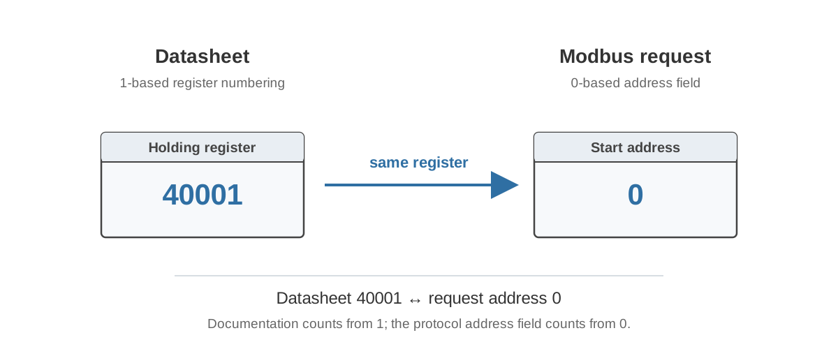
Register addressing is one of the simplest examples.
The first holding-register location may appear as:
| Representation | First location |
|---|---|
| Modbus protocol offset | 0 |
| One-based register number | 1 |
| Holding-register reference | 40001 |
These can all describe the same logical location.
If the documentation contains only:
Address: 1
the integrator still has to determine what 1 means.
A PLC configuration may expect a zero-based protocol offset. Another tool may show one-based register numbers. A manual may use 4xxxx references.
The dangerous case is not always a timeout.
Suppose the intended map is:
| Protocol offset | Value |
|---|---|
| 100 | Supply air temperature |
| 101 | Supply air setpoint |
If the integration is shifted by one register, the device can reply normally with the supply air setpoint. The number may even look reasonable.
The communication works. The integration is still wrong.
For the addressing problem in more detail, see Modbus Addressing: 40001, 0-Based and 1-Based.
A register value does not explain itself
Receiving a 16-bit register does not tell the integrator what those bits represent.
Consider this raw value:
0xFF9C
It can be interpreted as:
| Data type | Value |
|---|---|
UINT16 | 65436 |
INT16 | -100 |
If the register represents temperature as INT16 x0.1 °C, the actual value is:
-100 x 0.1 = -10.0 °C
Nothing in the Modbus response itself tells the BMS that.
The register map has to provide that information.
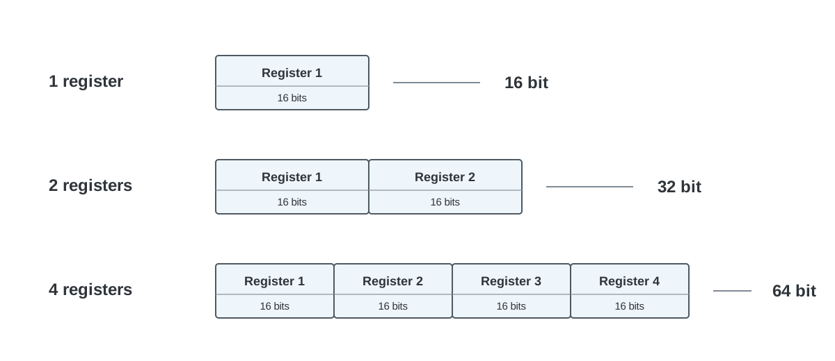
The same problem becomes more visible with 32-bit values because the integrator needs to know both the data type and how multiple registers are combined.
If the documentation says only:
Supply temperature
Address: 120
the engineer still has several unanswered questions.
Is it INT16, UINT16 or FLOAT32? Does it use one register or two? Is there scaling? What is the unit? If it uses two registers, what is the word order?
An experienced Modbus engineer can test different interpretations. That does not mean they should have to.
A successful value can still have the wrong meaning
Sometimes the numeric conversion is correct but the function of the register is not clear.
Consider a register named:
Night cooling
0 = Off
1 = On
What happens when the BMS writes 1?
It could mean:
- enable the automatic night cooling function
- request night cooling
- force night cooling to run
- report that night cooling is currently active
These are different functions.
The firmware developers may know exactly what the register means. The integrator only sees the name and value definitions.
Names such as Enable, Request, Command, Active, Status and Feedback should therefore be used consistently and described when the effect is not obvious.
This becomes increasingly important as the Modbus device becomes more intelligent. A room controller, heat pump or AHU controller contains its own logic. Writing to the device does not necessarily correspond directly to changing a physical output.
Writable values create another layer of uncertainty
A table that marks a register as R/W tells the engineer that it can be written. It does not necessarily tell them what happens after the write.
For a writable setpoint, useful information may include:
- accepted range
- actual resolution
- what happens to unsupported values
- when the value becomes active
- what a later read returns
- whether the value survives a restart
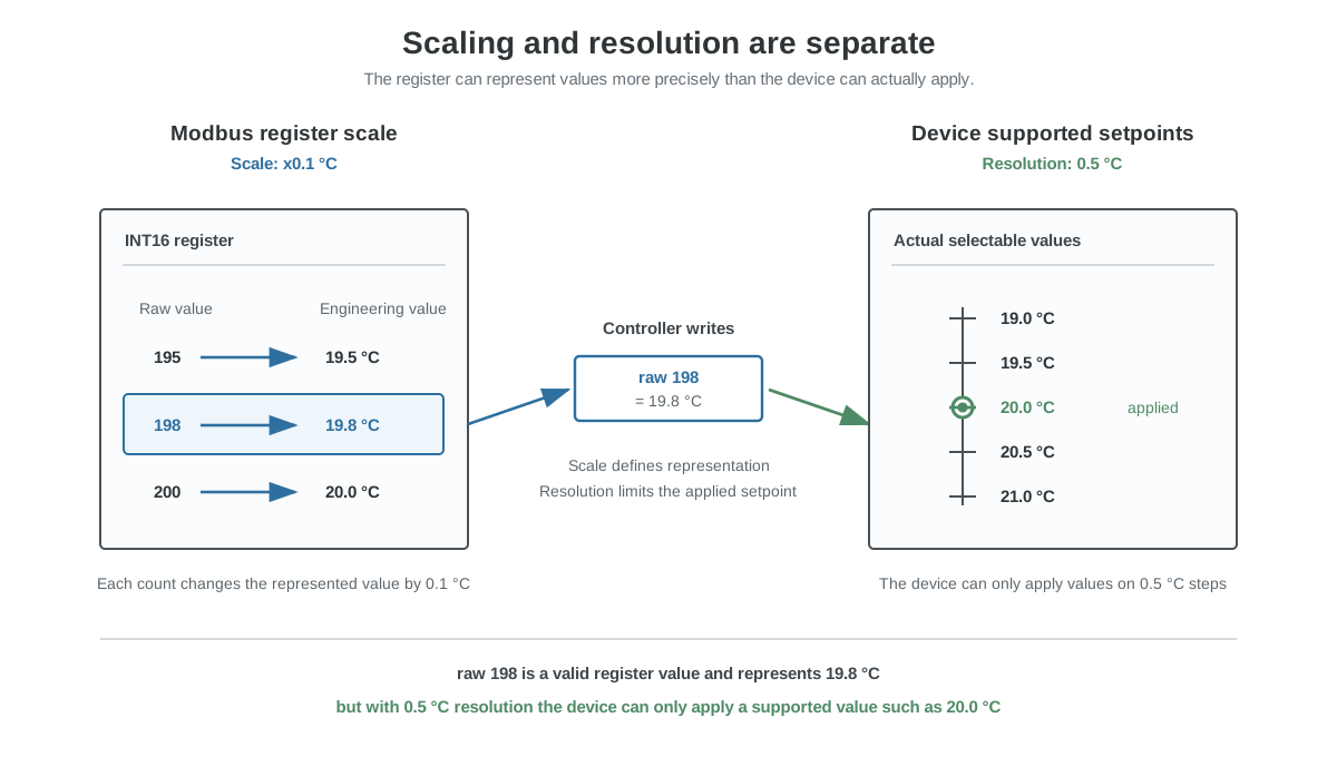
Consider a temperature setpoint represented in 0.1 °C counts.
The BMS writes:
198 = 19.8 °C
The device supports only 0.5 °C increments and stores:
200 = 20.0 °C
On the next read, the BMS receives 200.
Did the original write fail?
No. The device normalized the value to its actual resolution.
But unless that behaviour is documented, the controller and device can disagree about what successful operation looks like. In some implementations this can even lead to repeated writes when the controller continuously tries to restore the original value.
Physical communication can introduce another set of assumptions
Some integration failures occur before the register map is even used.
For Modbus RTU over RS-485, the engineer also needs the physical interface to be understandable.
One common example is A/B terminal naming. The labels used by different manufacturers are not always consistent enough to assume polarity from the letters alone. The documentation should therefore provide enough information to connect the interface without trial and error.
The same principle applies to product-specific requirements such as supported serial settings, termination arrangements, communication timing or limitations on request sizes.
These details should be documented according to the actual product rather than assumed to be understood because the interface uses Modbus.
Trial and error is not a good interface specification
Experienced automation engineers are often very good at making poorly documented devices work.
They can:
- swap RS-485 conductors
- try neighbouring register addresses
- test different function codes
- change signed and unsigned interpretations
- swap 32-bit words
- experiment with scaling
- capture and decode raw Modbus frames
Eventually, they may find the correct combination.
That can make the integration look successful while hiding a product-interface problem.
If every customer has to rediscover the same addressing convention, scaling rule or undocumented setting, the cost of that ambiguity is repeated on every project.
One hour spent clarifying the interface once at the manufacturer can otherwise become one hour of troubleshooting for each integrator who uses the product.
Look at the problem from the support side
Repeated integration questions are useful product feedback.
For example, if support repeatedly receives questions such as:
- Which address should I enter in my PLC?
- Should I use Function Code 03 or 04?
- Is this value signed?
- What scaling should I use?
- Which word comes first?
- What does this status bit mean?
- Why does the value change after I write it?
- Does the communication setting require a restart?
the solution should not always be another support answer.
If several customers ask the same question, that information probably belongs in the interface documentation.
This is particularly important for OEM products that may be integrated by many different BMS companies, PLC programmers and system integrators. The manufacturer cannot assume that the same person or company will perform every integration.
Give the device to an engineer who has never seen it
A useful test is simple.
Give an experienced automation engineer:
- the production device
- the released manual
- the released Modbus register map
- a normal Modbus client or PLC
- the normal connection accessories
Do not give them internal development notes.
Then ask them to perform a few normal integration tasks:
- Establish communication.
- Read one important measurement.
- Convert it to the correct engineering value.
- Read the device operating state.
- Change one normal writable setting.
- Read the setting back and confirm the result.
- Identify how the device reports a fault.
Watch where they need to stop and ask a question.
Each question exposes information that may be missing, unclear or difficult to find.
This test is different from asking the firmware developer to demonstrate that Modbus works. The firmware developer already knows the answers.
The purpose is to test whether the public interface explains itself well enough for the intended customer.
What a usable Modbus interface should tell the integrator
The exact documentation depends on the product, but an integrator should normally be able to determine the following without reverse engineering the device:
| Area | Information the integrator needs |
|---|---|
| Communication | Interface type, supported settings and defaults |
| Addressing | Register type, function code and addressing convention |
| Data | Type, signedness, register count and byte/word order where relevant |
| Engineering value | Scale, offset, unit and valid range |
| Writing | Access, resolution, validation, activation and readback behaviour |
| States | Clear definitions for commands, enables, status, alarms and bit fields |
| Compatibility | Firmware applicability and important changes between versions |
Not every device needs a complicated manual. A simple sensor may need only a small table.
The requirement is that the table contains the information needed to integrate the actual product.
Integration difficulty becomes part of the product
A device does not compete only on hardware specifications.
From the customer’s perspective, the total effort also includes the time needed to connect the device, understand its data and make it work reliably with the rest of the automation system.
Two technically similar products can therefore create very different project costs.
One may take an engineer 20 minutes to integrate using a clear register map and tested examples. Another may require several calls to technical support before the same information can be established.
That integration effort is experienced as part of the product whether or not it appears on the hardware specification sheet.
For a practical approach to improving the interface itself, see Designing Modbus Register Maps That Integrators Can Actually Use.
Before releasing a new product or firmware version, also see How to Test a Modbus Device Before Release.
If you manufacture a Modbus device and want an external review of the register map, documentation or integration behaviour, see LumiBMS Modbus consulting.