
Designing Modbus Register Maps That Integrators Can Actually Use
A Modbus register map is part of the product. Once customers build PLC code, BMS templates, graphics and alarm logic around published addresses, the map becomes a public interface that the manufacturer has to maintain.
The protocol itself can work perfectly while the product is still difficult to integrate. Important values can be hard to find, addressing can be ambiguous, writable registers can behave differently from the table and firmware updates can move values that customers already depend on.
A useful design question is therefore not “Which internal variables can we expose?” It is:
What does an external system need from this product, and how can we make that path obvious and stable?
The material below is condensed from a longer manufacturer-focused register-map design manuscript. The central idea is that integration effort is part of the product cost: ambiguity that takes one hour to resolve at the manufacturer can otherwise cost the same hour for every customer who integrates the device.
Start with the customer’s normal integration path
Do not build the public map by dumping an internal firmware structure into consecutive registers. Firmware is organised around implementation details. The public interface should be organised around customer use.
For a room sensor, the BMS normally cares first about temperature, CO2, humidity, occupancy and device health. Display brightness, calibration history, manufacturing data and service counters may be useful, but they should not hide the values that are read continuously.
A useful high-level structure can be:
| Address area | Purpose | Typical use |
|---|---|---|
| 0-15 | Primary measurements | Cyclic BMS polling |
| 16-31 | Reserved for measurement growth | Future backward-compatible additions |
| 32-47 | Commands and user adjustments | Normal external control |
| 48-63 | Reserved for command growth | Future additions |
| 64-95 | Status and alarms | Health and operating state |
| 96-127 | Configuration | Commissioning and occasional changes |
| 128+ | Service/diagnostics if needed | Troubleshooting and advanced use |
The exact ranges are not a Modbus standard and should not be copied blindly. The principle is more important: values used together should be easy to find and, where practical, easy to read together.
Your manuscript makes the same point directly: important process values should be grouped according to how the customer consumes them rather than by internal data type or firmware layout.
Make addressing impossible to misunderstand
A column called Address is often not enough.
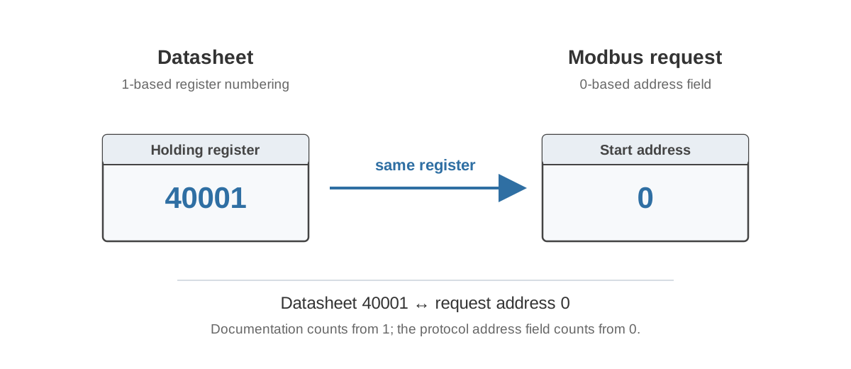
The same holding-register location may be represented as:
| Representation | First location |
|---|---|
| Modbus protocol offset | 0 |
| One-based register number | 1 |
| Holding-register reference | 40001 |
The Modbus request contains the protocol address, not the number 40001 as a literal forty-thousand-range address. If historical 4xxxx references are useful for your customers, show them in a separate clearly labelled column.
For example:
| Offset | Reference | FC | Name |
|---|---|---|---|
| 0 | 40001 | 03 | Room temperature |
| 1 | 40002 | 03 | CO2 concentration |
| 2 | 40003 | 03 | Relative humidity |
Then state the convention in one sentence near the table:
All addresses in this document are zero-based Modbus protocol offsets. Offset 0 corresponds to holding-register reference 40001.
The exact wording can vary, but nobody should need to determine the address base experimentally. The source manuscript highlights that a successful read from the neighbouring register can be more dangerous than a complete communication failure because the wrong value may still look believable.
For a deeper explanation, see Modbus Addressing: 40001, 0-Based and 1-Based.
Document the data representation, not only the variable name
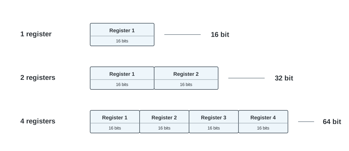
A Modbus register is 16 bits. The protocol does not tell the customer whether those bits represent INT16, UINT16, a bit field or half of a 32-bit value.
For every public value, document the properties that change how the customer interprets it:
- data type and signedness
- number of registers
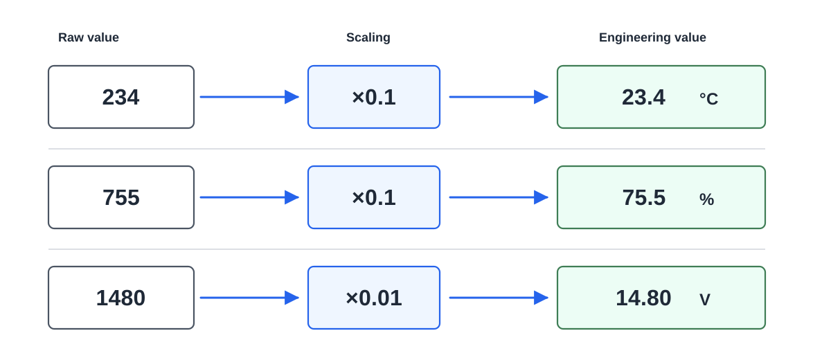
- scale
- engineering unit
- valid range
- application resolution when it differs from numeric representation
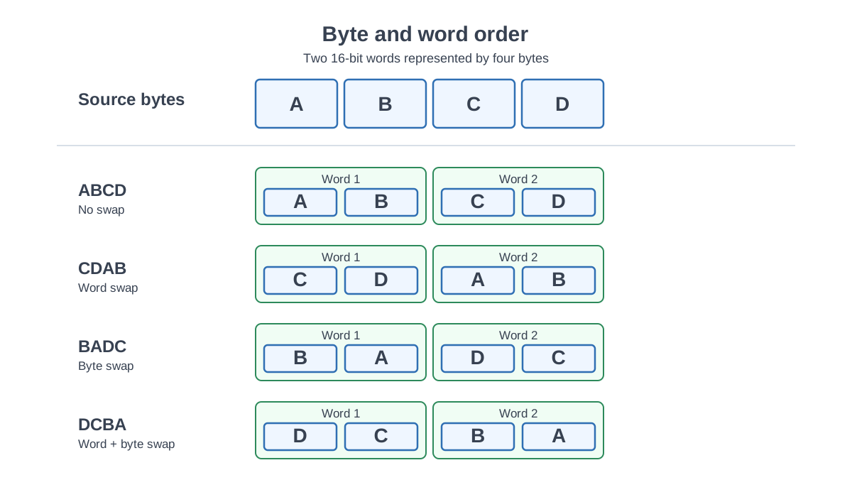
- byte and word order for multi-register values
Simple scaled integers are often excellent for building automation values because they are easy to consume across many PLC and BMS platforms. A room temperature can be INT16 x0.1 °C, while CO2 can be UINT16 x1 ppm. FLOAT32 is useful when the application needs it, but it should not be chosen merely because the processor uses floating point internally.
Scaling and resolution are separate
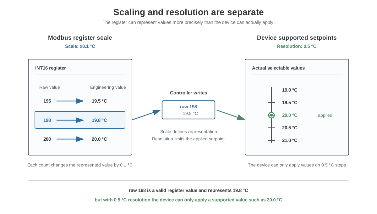
Suppose a temperature setpoint is represented as INT16 x0.1 °C, but the device actually supports only 0.5 °C steps.
The table should say both:
Scale:      x0.1 °C
Resolution: 0.5 °C
Otherwise an external controller can write 19.8 °C and reasonably expect the device to keep exactly that value even though the product can only use 20.0 °C.
Document what a function does, not only what bits contain
A register called Night cooling with values 0 = Off and 1 = On can still be ambiguous. Writing 1 might start cooling immediately, enable an automatic algorithm, request operation subject to conditions or simply report that the function is already active.
Use functional terms deliberately:
| Term | Recommended meaning |
|---|---|
| Enable | Allows an automatic function to operate when its conditions are fulfilled |
| Command | Requested state or value from the external system |
| Request | External request that may still be limited by device logic |
| Active | Function is currently operating |
| Status | Current internal state reported by the device |
| Feedback | Measured or confirmed physical state |
| Available | Function can currently operate |
| Fault | Abnormal condition is present |
A manufacturer does not have to use exactly this vocabulary. The important part is consistency and a description that explains what changing the register causes.
This matters especially in intelligent controllers. An AHU controller is not a remote I/O module. A BMS enable can give internal logic permission to operate without directly energising an output. Your manuscript explicitly separates enable, request, active state and physical feedback for this reason.
Writable registers need a validation and readback policy
R/W is not enough documentation for a writable parameter.
The customer also needs to know:
- accepted range
- accepted step or resolution
- what happens outside the range
- whether unsupported values are rejected, clamped or normalized
- what a later read returns
- when the new value becomes active
- whether the value survives restart
- whether writing it changes other registers or logic
A small resolution mismatch can become a hardware problem
One useful field case is a controller that writes raw value 198. The device accepts the request but normalizes the effective value to 200. The controller reads 200, decides its desired value 198 has not been applied and writes 198 again.
If the setting is stored in EEPROM, the sequence can repeat indefinitely and cause unnecessary nonvolatile-memory writes. Communication is successful the entire time. The failure is an interface mismatch between the controller’s write/readback assumption and the device’s actual resolution.
Your manuscript describes this exact mechanism and notes several ways it could be prevented: document the real resolution, reject unsupported values, normalize on the client side, or avoid a physical EEPROM write when the effective value has not changed.
Consider separating frequently controlled values from persistent configuration. An active setpoint can live in RAM and be updated often, while a default setpoint or calibration parameter can be stored persistently and changed only during commissioning.
Treat communication settings as product features
Device address, baud rate and parity look simpler than the application map, but nothing else works until these settings do.
Support only options that are genuinely implemented and tested. A fixed 9600, 8E1 product can be easier to integrate than a device that advertises six baud rates and three parity modes but behaves inconsistently in some combinations.
If communication settings can be changed through Modbus, document the activation sequence. When a new address or baud rate takes effect is part of the interface.
The complete customer workflow should be tested:
- Connect with factory settings.
- Read current settings.
- Write the new setting.
- Receive the documented response.
- Activate the setting.
- Reconnect with the new configuration.
- Power-cycle the device.
- Verify persistence.
Design failure behaviour before the sensor fails
A Modbus server can remain fully responsive while the measurement behind one register is dead. Communication health and process-value validity are different concepts.
Suppose a room sensor has reported 21.4 °C and the sensing element fails. Retaining the last valid value may be a reasonable design choice, but only if the receiving system can tell that the measurement is stale.
A simple interface could provide:
| Offset | Value |
|---|---|
| 0 | Room temperature, last valid value retained |
| 1 | CO2 concentration |
| 2 | Measurement/alarm status word |
If the temperature sensor fails, the room-temperature register can stay at 21.4 °C while a fault bit becomes active. The BMS can then decide whether to gray out the value, alarm it, stop using it for control or fall back to another sensor.
The source material emphasizes this distinction: a believable frozen measurement can remain unnoticed because Modbus communication itself is healthy.
Keep alarm words coherent
Bit fields work well when all bits answer one high-level question. A 16-bit alarm word can be designed so that 0 means no active alarms and any nonzero value means at least one alarm is active.
Do not mix unrelated normal statuses into the same word merely because spare bits exist. If bits represent sensor fault, holiday mode, display backlight and fan command at the same time, a simple alarm word > 0 test no longer means anything useful.
Group normal polling into sensible contiguous blocks
Modbus RTU is request-response communication. Every extra request consumes bus time and creates another opportunity for delay, timeout or retry.
If temperature, CO2, humidity and occupancy are all needed cyclically, place them in a compact readable block where practical. Do not scatter them around the address space only because the internal variables belong to different C structures or data types.
At the same time, think about gaps. If a BMS needs registers 10, 12 and 14, it may reasonably request the full range 10 to 14. If addresses 11 and 13 cause the entire request to fail, the map may be technically valid but awkward to consume. Keep large reserved regions between functional blocks rather than inside the most frequently polled block when possible. This trade-off is described in the manuscript’s polling and robustness section.
Preserve published meanings across firmware versions
A published register address is a compatibility commitment.
Adding a new humidity value into reserved space is usually cheap for the customer. Inserting it in the middle of the existing map and shifting every later address can break PLC programs, device libraries, graphics, trends and alarms across installed systems.
Backward compatibility includes more than the number itself. Changing any of these can break an old integration:
- data type
- scale
- unit
- write behaviour
- alarm bit meaning
- default value or dependency
Prefer additive changes. If the product family is expected to evolve, reserve realistic space near the functions that are likely to grow. Do not reserve thousands of addresses without a reason; the goal is stable evolution, not a mathematically neat empty map.
Your manuscript’s compatibility section recommends exactly this: preserve old addresses and use reserved locations for new features where practical.
A public register table should contain enough information to implement the interface
A useful core table can include:
| Field | Why it matters |
|---|---|
| Protocol offset | Actual address used in the request |
| Reference | Optional 4xxxx representation |
| Function code | Supported operation |
| Name | Functional identifier |
| Description | Meaning and important behaviour |
| Type | INT16, UINT16, FLOAT32, bit field, etc. |
| Access | R, W or R/W |
| Scale | Raw-to-engineering conversion |
| Unit | °C, ppm, Pa, %, V, etc. |
| Valid range | Application limits |
| Resolution | Smallest supported step where relevant |
| Default | State observed after reset/power-up |
| Persistence | RAM, EEPROM/flash or other behaviour |
| Dependencies | Registers or modes that affect meaning |
| Failure behaviour | What happens when source data is invalid |
| Write behaviour | Validation, clamping, normalization and readback |
Not every simple measurement needs a paragraph. Complex writable values, bit fields, enums and dependencies usually do.
The register map should also include a short integration overview before the big table: communication defaults, addressing convention, supported function codes, recommended polling block and important rules such as fixed units or persistence behaviour.
Review the map before the firmware is frozen
The best time to move a register is before anybody outside the development team has integrated it.
Give the released documentation and a device to someone who was not involved in the firmware implementation. Ask them to integrate the product without verbal corrections. Every question they need to ask is evidence that the public interface may still contain hidden assumptions.
Review both individual rows and the shape of the whole map:
- Are the primary measurements easy to find?
- Can values used together be read together?
- Are commands, enables, statuses and feedback clearly different?
- Is addressing explicit?
- Are type, scale, unit, range and resolution defined?
- Is write/readback behaviour defined?
- Are persistent and volatile values distinguishable?
- Does a sensor fault remain visible even if Modbus communication continues?
- Are alarm bits coherent?
- Can the map grow without shifting existing addresses?
- Will the same address still mean the same thing after the next firmware release?
The manuscript’s release checklist extends this into invalid requests, long-duration polling and regression testing against the old interface.
For a complete manufacturer-side test procedure, see How to Test a Modbus Device Before Release.
The target is a boring integration
The best Modbus interface is usually the one the integrator stops thinking about. Communication works with the settings in the manual. Temperature looks like temperature. An enable enables a function. A status reports status. A failed sensor identifies itself as failed. Firmware updates do not silently move addresses.
The product can then disappear into the larger automation system and the engineer can focus on the building process instead of reverse engineering the device.
If you manufacture a Modbus device and want an integrator-side review of the register map, documentation or test plan, see Modbus consulting.