Wireless Radio Fundamentals for Building Automation
This guide explains the most important radio fundamentals behind wireless building automation systems. It focuses on frequency bands, wavelength, free-space path loss, diffraction, building penetration, interference, and practical antenna placement.
The goal is to understand why one wireless system works well in a plant room, basement, riser, office floor, or apartment building, while another system may fail even if the datasheet range looks good.
Overview
Wireless communication in building automation is affected by much more than the protocol name. The real performance depends on the frequency band, transmit power, receiver sensitivity, modulation, antenna design, installation position, building materials, interference, and gateway placement.
For building automation, the most common frequency areas are:
- 433 MHz
- 868 MHz in Europe
- 915 MHz / 902–928 MHz in some regions
- 2.4 GHz
- 5 GHz and 6 GHz, mainly for Wi-Fi and IT networks
Sub-GHz systems such as 433 MHz, 868 MHz and 915 MHz usually provide better range and building penetration than 2.4 GHz systems. However, 2.4 GHz has a very large device ecosystem and is used by Wi-Fi, Bluetooth, BLE, Zigbee, Thread, Matter over Thread, WirelessHART and many proprietary systems.
1.1 Frequency bands
A frequency band is the part of the radio spectrum where a wireless system transmits.
Frequency is measured in hertz. One hertz means one cycle per second.
433 MHz = 433,000,000 cycles per second
868 MHz = 868,000,000 cycles per second
2.4 GHz = 2,400,000,000 cycles per second
The frequency affects:
- range
- wall penetration
- antenna size
- interference
- legal limits
- data rate
- gateway placement
- battery life
- device availability
Typical building automation examples:
| Frequency area | Typical use |
|---|---|
| 433 MHz | simple sensors, remote controls, older/proprietary systems |
| 868 MHz | European wM-Bus, OMS, LoRaWAN EU868, EnOcean, KNX RF, proprietary sensors |
| 915 MHz / 902–928 MHz | LoRaWAN US915 and other sub-GHz systems in some regions |
| 2.4 GHz | Wi-Fi, BLE, Zigbee, Thread, Matter over Thread, WirelessHART |
| 5 GHz / 6 GHz | Wi-Fi, high-bandwidth IT devices, gateways, cameras |
In Europe, many sub-GHz short-range devices are covered by ETSI rules in the range below 1 GHz. For example, ETSI EN 300 220 covers short-range devices operating in the frequency range from 25 MHz to 1,000 MHz.
1.2 Wavelength
A radio wave has a wavelength. Wavelength is the physical distance of one full wave cycle.
The basic relationship is:
wavelength = speed of light / frequency
or:
λ = c / f
where:
| Symbol | Meaning |
|---|---|
λ | wavelength in metres |
c | speed of light, about 300,000,000 m/s |
f | frequency in hertz |
Approximate wavelengths:
| Frequency | Approx. wavelength |
|---|---|
| 433 MHz | 69 cm |
| 868 MHz | 35 cm |
| 915 MHz | 33 cm |
| 2.4 GHz | 12.5 cm |
| 5 GHz | 6 cm |
The higher the frequency, the shorter the wavelength.
This matters because wavelength affects how radio waves interact with walls, metal, openings, corners, people, water, pipes and technical rooms.
1.3 Sub-GHz vs 2.4 GHz
Sub-GHz means frequencies below 1 GHz, such as 433 MHz, 868 MHz and 915 MHz.
In building automation, sub-GHz is often used for:
- wireless M-Bus
- OMS metering
- LoRaWAN
- EnOcean
- KNX RF
- long-range battery sensors
- proprietary meter and sensor systems
2.4 GHz is used for:
- Wi-Fi
- Bluetooth
- Bluetooth Low Energy
- Zigbee
- Thread
- Matter over Thread
- WirelessHART
- many smart building and smart home devices
A simple comparison:
| Topic | Sub-GHz | 2.4 GHz |
|---|---|---|
| Range | usually better | usually shorter |
| Wall penetration | usually better | usually weaker |
| Antenna size | larger | smaller |
| Data rate | usually lower | often higher |
| Device ecosystem | more regional | very global |
| Smartphone support | usually no | yes, through Wi-Fi/BLE |
| Congestion | often lower | often high |
| Typical use | meters and low-power sensors | room devices, Wi-Fi, BLE, mesh |
A practical rule:
Use sub-GHz when range, basement coverage, plant-room coverage or long battery life is important. Use 2.4 GHz when you need smartphone compatibility, room-level mesh, Wi-Fi, BLE or a large global device ecosystem.
1.4 Free-space path loss
Free-space path loss means the signal becomes weaker as it travels away from the transmitter.
Even in perfect free space, with no walls and no interference, the received signal power decreases with distance.
The main reason is spreading.
When a transmitter radiates energy, the radio wave spreads outward. At a longer distance, the same transmitted energy is spread over a larger area.
The surface area of a sphere is:
A = 4πd²
where:
| Symbol | Meaning |
|---|---|
A | surface area |
d | distance from the transmitter |
If the distance doubles, the surface area becomes four times larger. The same energy is now spread over four times the area, so the received power is lower.
Free-space path loss also depends on wavelength:
FSPL = (4πd / λ)²
Because wavelength depends on frequency, higher frequencies have more free-space path loss at the same distance.
In decibels, the common formula is:
FSPL(dB) = 20 log10(d) + 20 log10(f) + K
The important part is:
20 log10(f)
This means that path loss increases as frequency increases.
Example comparison:
Frequency ratio = 2400 MHz / 868 MHz ≈ 2.76
Path-loss difference = 20 log10(2.76) ≈ 8.8 dB
So, at the same distance in free space, 2.4 GHz has about 8.8 dB more free-space path loss than 868 MHz.
A rough power comparison:
| Difference | Approx. received power |
|---|---|
| 3 dB | half |
| 6 dB | one quarter |
| 9 dB | one eighth |
This is one reason why 868 MHz often works better than 2.4 GHz in long-range building sensor applications.
However, this does not mean that 868 MHz always wins. The final result also depends on receiver sensitivity, antenna quality, modulation, transmit power, interference, gateway placement and protocol behaviour.
Visual example: signal loss in a 10 m × 10 m room
The figure below shows a simplified top-down example of how a radio signal becomes weaker with distance and obstacles. The transmitter is shown as 100 mV only to make the voltage loss easy to visualize. In real RF work, transmitters are normally specified by power such as dBm or mW, not by mV.
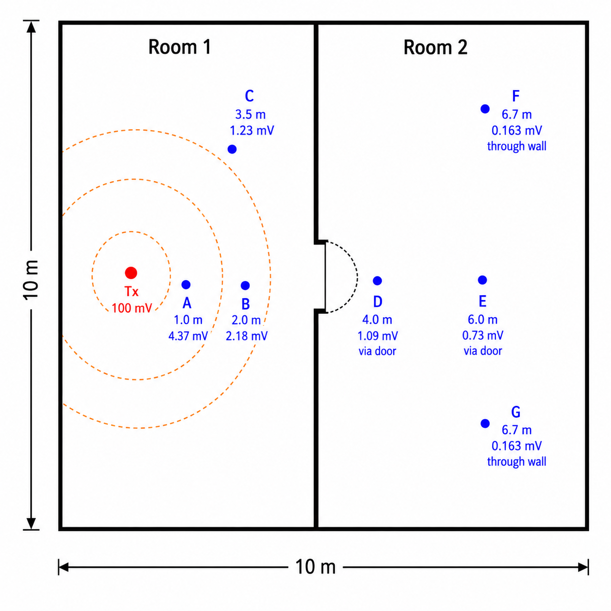
In the example, the signal becomes smaller as the distance from the transmitter increases. Points D and E are reached through the doorway, so the signal is mainly affected by distance. Points F and G are behind the wall, so an additional wall loss is included.
The important idea is not the exact number at each point. The important idea is:
Distance reduces the received signal, and walls or other obstacles reduce it even more.
In real buildings, the values would depend on the frequency, antenna orientation, wall material, receiver sensitivity, reflections, diffraction, and interference.
1.5 Diffraction
Diffraction is the ability of a wave to bend or spread around edges and openings.
Radio does not behave like a perfectly straight laser beam. When a radio wave reaches the edge of a wall, doorway, shaft, corner or obstacle, part of the wave can spread into the shadow area behind the obstacle.
This is easier when the wavelength is large compared with the obstacle or opening.
Longer wavelengths diffract better than shorter wavelengths.
| Frequency | Wavelength | Diffraction behaviour |
|---|---|---|
| 433 MHz | ~69 cm | better bending around obstacles |
| 868 MHz | ~35 cm | good bending around building-scale edges |
| 2.4 GHz | ~12.5 cm | more easily shadowed |
| 5 GHz | ~6 cm | behaves more like light |
A simple mental model:
Lower frequency waves are physically larger, so they are more forgiving around corners, openings and obstacles.
This is why a sub-GHz sensor may still reach a gateway from behind a corner or from a basement corridor, while a 2.4 GHz device may need a better line of sight or a stronger mesh.
Diffraction can happen around:
- wall corners
- door openings
- stairwell edges
- ventilation shaft openings
- concrete pillars
- roof edges
- corridor intersections
- pipework and ductwork edges
Diffraction is not the same as wall penetration. In real buildings, the receiver may get a mixture of:
- direct signal
- reflected signal
- diffracted signal
- scattered signal
- signal that passed through walls
This mixture is called multipath.
1.6 Penetration, reflection and absorption
When a radio wave reaches a material, several things can happen.
| Effect | Meaning |
|---|---|
| Penetration | some energy passes through the material |
| Reflection | some energy bounces away from the material |
| Absorption | some energy is converted to heat or lost inside the material |
| Scattering | energy is redirected in many directions |
| Diffraction | energy bends around edges and openings |
Different materials affect radio signals differently.
| Material / object | Typical effect |
|---|---|
| Drywall | usually low attenuation |
| Wood | usually moderate attenuation |
| Glass | variable, can be worse if coated |
| Concrete | significant attenuation |
| Reinforced concrete | high attenuation because of steel rebar |
| Metal cabinet | very high attenuation, often behaves like a shield |
| Cable tray | reflection and shadowing |
| Ductwork | reflection and shadowing |
| Water pipes / tanks | absorption and shadowing |
| People | absorption, especially at 2.4 GHz |
| Plant rooms | difficult because of metal, motors, pipes, concrete and electrical noise |
A signal path through an open office is very different from a signal path through a basement plant room.
1.7 Multipath
Multipath means that the same transmitted signal reaches the receiver through several different paths.
For example, the receiver may hear:
- one signal directly from the transmitter
- one reflected from a metal duct
- one reflected from a concrete wall
- one diffracted around a doorway
- one scattered by pipework
These copies arrive at slightly different times and phases. They can add together or cancel each other.
Multipath can cause:
- unstable RSSI
- dead spots
- packet loss
- good signal in one exact position but poor signal 30 cm away
- worse performance when doors, people or equipment positions change
This is why moving an antenna slightly can sometimes improve reception a lot.
Practical example:
Sensor works poorly on one side of a metal cabinet.
Sensor works better when moved 50 cm higher or closer to the doorway.
The protocol did not change. The radio environment changed.
1.8 Fresnel zone
Radio line of sight is not only a thin straight line between antennas.
The radio wave needs space around the direct path. This space is called the Fresnel zone.
If objects enter the Fresnel zone, the signal can become weaker even if there is visual line of sight.
A simplified view:
TX antenna        Fresnel zone         RX antenna

     |          (               )          |
     |---------(-----------------)---------|
     |          (               )          |
For building automation, this means:
- do not hide antennas behind cable trays
- do not place antennas directly against concrete ceilings
- do not mount gateways behind metal ducts
- do not place the antenna inside a panel if you expect building-wide coverage
- leave open space around the antenna
A practical rule:
Visual line of sight is useful, but radio line of sight also needs clearance around the path.
1.9 Antenna basics
An antenna converts electrical energy into radio waves and radio waves back into electrical energy.
The antenna must match:
- the frequency band
- the connector
- the device impedance
- the installation environment
- the polarization
- the required radiation pattern
A common simple antenna type is a quarter-wave antenna.
Approximate quarter-wave lengths:
| Frequency | Quarter wavelength |
|---|---|
| 433 MHz | ~17 cm |
| 868 MHz | ~8.6 cm |
| 915 MHz | ~8.2 cm |
| 2.4 GHz | ~3.1 cm |
This is why 2.4 GHz devices can have small antennas. Sub-GHz devices need larger antennas, or they use compact antennas with design compromises.
A smaller antenna is not automatically worse, but it must be designed correctly for the frequency and the enclosure.
1.10 Antenna polarization and orientation
Many simple antennas are linearly polarized.
This means the electric field has a main orientation. If one antenna is vertical and the other is horizontal, the received signal may become much weaker.
Common practical rule:
Keep transmitter and receiver antennas in the same orientation when possible.
Usually this means:
Vertical antenna on the gateway
Vertical antenna on the sensor
For a vertical whip antenna:
Good:

|
|
|

Bad:

---------
This is not always possible with small wall sensors because the antenna may be internal. In that case, follow the manufacturer’s mounting instructions.
If reception is poor, rotating the device or gateway antenna can change the result.
1.11 Antenna placement
Antenna placement is often more important than the protocol choice.
A good wireless protocol with bad antenna placement can perform badly. A moderate protocol with good antenna placement can perform well.
Avoid metal enclosures
Metal blocks and reflects radio waves.
Bad:
Gateway inside metal automation cabinet
Antenna inside cabinet
Cabinet door closed
Better:
Gateway inside cabinet
External antenna outside cabinet
Short antenna cable
Best:
Gateway or antenna outside metal cabinet
Antenna high on wall
Clear space around antenna
Away from electrical noise
A metal cabinet behaves partly like a Faraday cage. Even if the gateway electronics work correctly, the antenna may not radiate properly.
Keep distance from metal
Avoid placing antennas directly against:
- metal cabinets
- ventilation ducts
- cable trays
- steel beams
- electrical panels
- pipe bundles
- motors
- pumps
- VFD cabinets
For 868 MHz, the wavelength is about 35 cm and the quarter wavelength is about 8.6 cm. Even a few centimetres from metal can affect the antenna.
As a practical starting point, keep at least 10–20 cm away from small metal objects where possible. Keep more distance from large metal surfaces.
Mount gateways high
Higher placement usually helps building-wide reception.
Good positions:
- high on a wall
- near a corridor
- near a stairwell
- near an atrium
- near a riser or open shaft
- above furniture level
- away from large metal objects
Bad positions:
- under desks
- inside cabinets
- low near the floor
- behind ducts
- beside VFDs
- behind metal doors
- in the back of a technical room
Higher placement often improves:
- Fresnel clearance
- obstacle clearance
- corridor propagation
- chance of receiving reflected or diffracted paths
Use corridors and stairwells
Corridors can act as radio paths. A gateway near a corridor intersection may hear more devices than a gateway placed deep inside one room.
Stairwells and shafts can sometimes help vertical propagation between floors. However, reinforced concrete stairwells can also block signals. Always test.
Avoid water and people
Water absorbs radio energy. People are mostly water.
Avoid placing antennas:
- behind water tanks
- directly beside large water pipes
- behind heat exchangers
- behind HVAC coils
- in crowded occupied locations if the signal path goes through people
- close to damp concrete if another position is available
This is especially important at 2.4 GHz, but sub-GHz can also be affected.
Avoid electrical noise
Keep antennas away from:
- variable frequency drives
- large motors
- switch-mode power supplies
- LED drivers
- inverters
- contactors
- transformers
- high-current cables
- lift machinery
- main switchgear
Electrical noise does not have to be on the same exact frequency to cause problems. It can reduce receiver performance or create a poor local RF environment.
Avoid long antenna cables
Antenna cables have loss. The longer the cable, the more signal is lost.
Bad:
Gateway -> 10 m cheap coax -> antenna
Better:
Gateway close to antenna
Short coax cable
Often the best solution is to move the whole gateway to a good RF location and run Ethernet or power to the gateway instead of using a long antenna cable.
If a long cable is unavoidable:
- use low-loss coax
- keep it as short as possible
- use correct connectors
- include cable loss in the link budget
- protect outdoor connectors from moisture
1.12 Building automation examples
Example 1: Wireless M-Bus heat meters
Meters are often located in cabinets, shafts, apartments, basements or technical rooms.
Good receiver placement:
- near risers or shafts
- outside metal cabinets
- high enough to avoid immediate obstacles
- away from electrical panels
- possibly multiple receivers in larger buildings
For meter reading, you may not need to receive every telegram. You need enough successful reads over time.
Evaluate:
- read success per day
- missed meters
- gateway location
- antenna position
- meter cabinet material
- encryption/key handling
- integration to the BMS or billing system
Example 2: LoRaWAN CO₂ sensors in a school
LoRaWAN can work well for battery-powered IAQ sensors.
Good gateway placement:
- central location
- high wall or ceiling position
- near corridor or atrium
- away from metal and VFDs
- Ethernet or PoE available
- not hidden above metal ceiling panels
Test:
- basement rooms
- classrooms at the far end of corridors
- plant rooms
- stairwells
- roof or outdoor areas
- packet loss and SNR, not only RSSI
Example 3: Zigbee or Thread room sensors
Zigbee and Thread usually use 2.4 GHz mesh.
Important:
- mains-powered routers form the mesh backbone
- battery sensors are usually sleepy end devices
- one gateway in a cabinet is usually not enough
- routers must be distributed around the building
- Wi-Fi channel planning matters
Good placement:
- coordinator/gateway central
- enough mains-powered router devices
- avoid metal cabinets
- avoid overlapping heavily with busy Wi-Fi channels
- test room-to-room paths
Example 4: BLE commissioning
BLE is often used for device commissioning with a phone.
Good BLE design:
- keep the antenna accessible
- do not hide the device behind metal covers
- test with real phones
- check both Android and iOS behaviour if relevant
- avoid relying on BLE for whole-building coverage unless there are enough BLE gateways
1.13 RSSI, SNR and packet loss
Do not judge wireless quality from one number only.
Common indicators:
| Indicator | Meaning |
|---|---|
| RSSI | received signal strength |
| SNR | signal-to-noise ratio |
| packet loss | how many messages are missed |
| join success | whether devices can join the network reliably |
| latency | how long the message takes |
| retry count | how often messages must be repeated |
| battery trend | whether poor radio conditions reduce battery life |
RSSI alone can be misleading.
A signal can have:
- strong RSSI but poor SNR because of interference
- weak RSSI but good SNR and reliable decoding
- good readings during testing but poor reliability after doors close or equipment starts
- good performance in one season and worse performance after changes in the building
For building automation, the most important practical value is often:
Does the point update reliably enough for its purpose?
For example:
- a heat meter can tolerate occasional missed telegrams
- a CO₂ sensor may need reliable updates every 5–15 minutes
- a leak alarm should be received quickly and reliably
- critical HVAC control should usually not rely on low-power wireless telemetry
1.14 Common installation mistakes
Antenna inside metal cabinet
The device may power up and the software may look correct, but radio performance is poor.
Fix:
- use an external antenna
- move the gateway outside the cabinet
- mount the antenna high and clear
Gateway placed too low
Low placement increases blockage from people, furniture, cabinets and equipment.
Fix:
- mount the gateway or antenna higher
- test from worst-case rooms
Antenna too close to metal
The antenna can detune and the radiation pattern can change.
Fix:
- increase distance from metal
- use a mounting bracket
- use an external antenna designed for the installation
Too much reliance on datasheet range
Datasheet range is often measured in ideal or open conditions.
Fix:
- perform site testing
- test with doors closed
- test in real rooms
- test after equipment is running
Wrong regional frequency version
A device made for EU868 is not the same as a device made for US915.
Fix:
- check the device frequency plan
- check the gateway frequency plan
- check local regulations
- check antenna frequency rating
Wrong antenna type
An antenna for 2.4 GHz will not work correctly for 868 MHz, and an 868 MHz antenna will not work correctly for 2.4 GHz.
Fix:
- use the correct antenna for the radio band
- check connector type
- check antenna gain and legal limits
1.15 Practical antenna placement checklist
Before final installation, check:
- Is the antenna inside a metal box?
- Is the antenna too close to metal?
- Is it near ducts, cable trays, pipes or switchgear?
- Is it near VFDs, motors, LED drivers or transformers?
- Is it low near the floor?
- Is there open space around the antenna?
- Is the antenna orientation correct?
- Is the antenna rated for the correct frequency?
- Is the connector correct?
- Is the coax cable short enough?
- Is the gateway central enough?
- Are corridors, stairwells or risers used intelligently?
- Have the worst-case rooms been tested?
- Have RSSI, SNR and packet loss been checked?
- Has the system been tested with doors closed?
- Has the system been tested with equipment running?
- Is the radio region correct?
- Is the installation legal with the selected antenna gain and transmit power?
1.16 Troubleshooting weak wireless communication
When wireless communication is unreliable, check the simple things first.
Step 1: Confirm frequency and region
Check:
- device frequency band
- gateway frequency band
- regional frequency plan
- antenna frequency rating
- local radio rules
Example:
EU868 device + US915 gateway = wrong combination
Step 2: Check antenna position
Check:
- inside metal or outside metal
- height
- orientation
- nearby metal
- nearby electrical noise
- cable length
- connector tightness
Step 3: Move the antenna slightly
Small movements can change multipath.
Try:
- 30 cm higher
- 50 cm away from cabinet
- closer to doorway
- closer to corridor
- vertical instead of horizontal
- outside the panel
Step 4: Check signal quality
Record:
- RSSI
- SNR
- packet loss
- missed messages
- join failures
- time of day
- equipment operating state
Step 5: Test worst-case locations
Do not test only near the gateway.
Test:
- basement
- plant room
- farthest room
- stairwell
- riser
- behind fire doors
- behind concrete walls
- inside meter rooms
- after tenants or furniture are present
Step 6: Add gateways or routers if needed
If placement cannot solve the issue:
- add another LoRaWAN gateway
- add another wM-Bus receiver
- add Zigbee/Thread router devices
- add BLE gateways
- move the gateway to a better location
- use an external antenna
Do not try to solve every radio problem with transmit power. More power is not always legal, and it does not always solve interference, dead spots or poor antenna placement.
1.17 ISM / SRD regulations
Many building automation radio devices use licence-free spectrum. Licence-free does not mean rule-free. It means the device can normally be used without applying for a separate radio licence, as long as it follows the technical limits for that band.
In Europe, many sub-GHz building IoT devices are treated as Short Range Devices (SRD). This is relevant for systems such as:
- wireless M-Bus
- OMS meters
- LoRaWAN EU868
- EnOcean
- KNX RF
- proprietary 868 MHz sensors
The most important practical limits are usually:
| Topic | Meaning |
|---|---|
| Frequency band | the device must use the correct regional band, such as EU868 |
| Transmit power | the radio may only transmit up to the allowed radiated power |
| Duty cycle | the device may only occupy the channel for a limited time |
| Channel spacing / bandwidth | the signal must fit inside the allowed channel arrangement |
| Antenna gain | changing the antenna can change the radiated power |
| Compliance | certified devices should be used according to manufacturer instructions |
For a building automation engineer, the key point is simple:
Use certified devices, use the correct regional version, and do not modify antennas or radio settings without checking the limits.
1.18 Duty cycle
Duty cycle limits how much time a device may transmit.
For example, if a channel has a 1% duty cycle, the device may transmit for only 1% of the time.
1 hour = 3600 seconds
1% of 3600 seconds = 36 seconds
So a 1% duty cycle means the device may transmit for a maximum of about 36 seconds per hour on that channel.
If the duty cycle is 0.1%:
0.1% of 3600 seconds = 3.6 seconds per hour
This is one reason why sub-GHz wireless systems are well suited for small messages, but not for continuous communication.
Good fit:
- temperature every 10 minutes
- CO₂ every 5–15 minutes
- meter readings
- leak alarms
- battery status messages
Poor fit:
- high-speed data
- video
- frequent large payloads
- continuous polling
- fast closed-loop control
- firmware updates over low-power radio
A small sensor message may only occupy the radio channel for a short moment. A large payload or a slow data rate can occupy the channel much longer. In systems such as LoRaWAN, lower data rates can improve range, but they also increase airtime. More airtime means more duty-cycle use and usually more battery consumption.
For building automation, this means:
Low-power radio is usually excellent for telemetry, but not for constant high-speed communication.
1.19 Transmit power and antenna gain
Transmit power is how much RF power the radio produces. It is usually specified in dBm or mW.
Useful conversions:
| Power | dBm |
|---|---|
| 1 mW | 0 dBm |
| 10 mW | 10 dBm |
| 25 mW | 14 dBm |
| 100 mW | 20 dBm |
| 1000 mW / 1 W | 30 dBm |
Antenna gain does not create extra energy. It focuses energy more in some directions and less in others.
A simple comparison:
| Antenna type | Behaviour |
|---|---|
| Low-gain omnidirectional antenna | broad coverage, often good indoors |
| High-gain omnidirectional antenna | more sideways focus, weaker upward/downward coverage |
| Directional antenna | strong in one direction, poor elsewhere |
This is important because a bigger antenna is not always better. A high-gain antenna may improve coverage in one direction but reduce coverage on other floors or behind the antenna.
Radiated power depends on the radio power, antenna gain and cable loss:
Radiated power ≈ transmitter power + antenna gain - cable loss
For example:
Transmitter power = 14 dBm
Antenna gain      = 2 dBi
Cable loss        = 1 dB

Radiated power ≈ 14 + 2 - 1 = 15 dBm
If the antenna is changed from 2 dBi to 8 dBi, the radiated power in the strongest direction increases by 6 dB. That is four times the power in that direction. This can improve range, but it can also exceed legal or certified limits.
Practical rule:
First fix antenna placement, gateway location and cable loss. Do not solve every radio problem by increasing transmit power or using a larger antenna.
1.20 From transmitted power to received voltage
Radio transmitters are normally specified by power, not voltage. However, received signal levels can be converted to an equivalent RF voltage at a receiver input.
Most RF systems use a 50 Ω impedance. Power and RMS voltage are related by:
P = V² / R
or:
V = √(P × R)
For example, 14 dBm is about 25 mW:
P = 0.025 W
R = 50 Ω

V = √(0.025 × 50)
V ≈ 1.12 V RMS
After the signal spreads through the building, the receiver may see only millivolts, microvolts, or even less.
Approximate received voltage examples for a 50 Ω receiver input:
| Received power | Equivalent RF voltage |
|---|---|
| -30 dBm | 7.07 mV RMS |
| -50 dBm | 707 µV RMS |
| -70 dBm | 70.7 µV RMS |
| -90 dBm | 7.07 µV RMS |
| -100 dBm | 2.24 µV RMS |
| -110 dBm | 0.707 µV RMS |
| -120 dBm | 0.224 µV RMS |
The received signal can be extremely small, but the receiver can still decode it if the signal is strong enough compared with the noise.
1.21 Simple link budget
A link budget estimates how much signal reaches the receiver.
A simplified formula is:
Received power =
transmit power
+ transmitter antenna gain
- transmitter cable loss
- path loss
- wall/building loss
+ receiver antenna gain
- receiver cable loss
Example:
Transmit power:              +14 dBm
Transmitter antenna gain:     +2 dBi
Transmitter cable loss:        0 dB
Free-space path loss:        -80 dB
Building/wall loss:          -25 dB
Receiver antenna gain:        +2 dBi
Receiver cable loss:          -1 dB
Calculation:
Received power = 14 + 2 - 0 - 80 - 25 + 2 - 1
Received power = -88 dBm
If the receiver sensitivity is -120 dBm, the link margin is:
Link margin = -88 - (-120)
Link margin = 32 dB
A larger margin usually means more reliable communication. A small margin may work during testing but fail when doors close, people move, equipment starts, or interference increases.
In real building automation installations, the most useful improvements are often:
- move the gateway higher
- move the antenna outside the cabinet
- shorten antenna cables
- avoid metal and VFDs
- use the correct antenna
- add another gateway or receiver
- reduce the number of walls in the path
- test from worst-case rooms
1.22 Practical tips
- Lower frequency usually gives better range and building penetration, but the whole radio system matters.
- 868 MHz is very important for European building IoT and metering.
- 2.4 GHz has the largest ecosystem, but it is also crowded.
- Free-space path loss increases with frequency.
- Longer wavelengths diffract better around building-scale obstacles.
- Metal cabinets are one of the most common causes of poor wireless performance.
- Antennas should usually be high, clear, outside metal and away from electrical noise.
- Do not use long antenna cables unless necessary.
- RSSI alone is not enough; check SNR and packet loss.
- Always test in the real building before final installation.
- Critical control should normally remain wired unless the wireless system is specifically designed and proven for that purpose.
Sources
- ETSI EN 300 220-1: Short Range Devices operating in the frequency range 25 MHz to 1,000 MHz: https://www.etsi.org/deliver/etsi_en/300200_300299/30022001/03.01.01_60/en_30022001v030101p.pdf
- LoRaWAN Regional Parameters, LoRa Alliance: https://resources.lora-alliance.org/technical-specifications/rp002-1-0-5-lorawan-regional-parameters
- The Things Network LoRaWAN Regional Parameters: https://www.thethingsnetwork.org/docs/lorawan/regional-parameters/
- Bluetooth Technology Overview: https://www.bluetooth.com/learn-about-bluetooth/tech-overview/
- Cisco community guidance on access point and antenna positioning: https://community.cisco.com/t5/networking-knowledge-base/quot-best-practices-quot-for-positioning-access-points-ap-s-and/ta-p/3118895