I/O Guide: Digital and Analog Inputs and Outputs
A Building Management System communicates with sensors, actuators, and other field devices through inputs and outputs, usually shortened to I/O.
Inputs bring information from the field to the controller.
Outputs send commands from the controller to field devices.
What is an I/O module?
An I/O module connects the controller to sensors, contacts, transmitters, and actuators. I/O stands for Input/Output.
DI and AI bring information from the field to the controller. DO and AO send commands from the controller to field devices.
The four basic I/O types are:
| Type | Name | Direction | Typical use |
|---|---|---|---|
| DI | Digital Input | Into controller | Fan status, alarm contact, occupancy |
| DO | Digital Output | Out of controller | Pump start, fan enable, relay control |
| AI | Analog Input | Into controller | Temperature, pressure, CO₂, humidity |
| AO | Analog Output | Out of controller | Valve position, damper position, VFD speed |
The interactive trainer below demonstrates four common examples:
- DI with a normally open contact
- DO controlling a pump
- AI with an NTC10k temperature sensor
- AO with a 0–10 V valve actuator
Digital Input (DI) — DI+ / DI− with NO contact
Digital Output (DO) — DO+/DO− driving a pump
Analog Input (AI) — AI+ at divider node, AI− to GND
Analog Output (AO) — AO+/AO− to Valve (0–10 V)
This guide goes much further than the four basic I/O types.
In real BMS installations you will encounter terms such as dry contact, wet contact, potential free, NO, NC, COM, relay output, 0–10 V, 2–10 V, 4–20 mA, PNP, NPN, sourcing, sinking, loop powered, galvanic isolation, floating control, and many others.
Understanding these terms makes wiring diagrams, controller datasheets, commissioning, and troubleshooting much easier.
Always check the documentation for the actual controller and field device before connecting wiring. Terminal functions, voltage limits, common connections, and supported signal types vary between manufacturers.
1. Understanding Inputs and Outputs
A controller sits between sensors and controlled equipment.
A simple control chain could look like this:
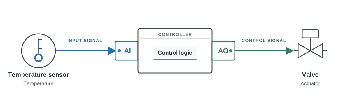
The sensor tells the controller what is happening.
The controller runs its control logic.
The output tells the field device what to do.
For example:
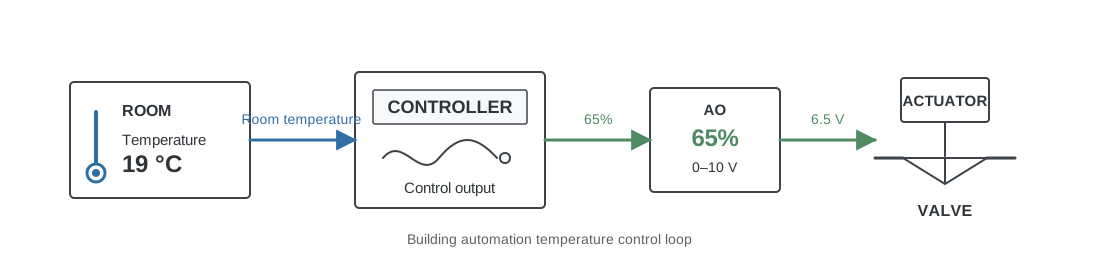
Digital signals work in the same way, except that they normally have only two logical states.
| State 0 | State 1 |
|---|---|
| OFF | ON |
| FALSE | TRUE |
| 0 | 1 |
| Open | Closed |
| Normal | Alarm |
| Stopped | Running |
2. Signal Type and Electrical Interface Are Different Things
One of the most important concepts in I/O is the difference between the logical I/O type and the electrical interface.
For example, a Digital Input could receive information through:
- A dry contact
- A 24 VDC signal
- A transistor output
- A relay
- A PNP sensor
- An NPN sensor
They are all Digital Inputs from the controller software point of view.
The electrical implementation is different.
A useful way to think about I/O is in three layers.
Layer 1: What does the signal represent?
DI
DO
AI
AO
Layer 2: How is the information electrically transmitted?
Open / closed contact
24 VDC
24 VAC
0–10 V
2–10 V
0–20 mA
4–20 mA
Resistance
Layer 3: How is the circuit implemented?
Relay
Transistor
Triac
PNP
NPN
Loop powered transmitter
Galvanically isolated input
Shared common
This distinction helps explain why two devices can both have a Digital Input while requiring completely different wiring.
3. Digital Inputs
A Digital Input, or DI, tells the controller whether something is in one of two states.
Typical examples include:
- Fan running
- Pump running
- Fan fault
- Pump fault
- Filter alarm
- Fire alarm
- Freeze protection alarm
- Door open
- Window open
- Occupancy detected
- High pressure switch
- Low pressure switch
- Flow switch
- Safety interlock
At the software level the controller normally sees something similar to:
| Boolean |
|---|
| FALSE |
| TRUE |
or:
| Numeric |
|---|
| 0 |
| 1 |
The electrical circuit that produces that state can vary considerably.
4. Dry Contacts
A dry contact is one of the most common concepts in building automation.
Dry contacts are also called:
- Potential free contacts
- Volt free contacts
- Voltage free contacts
A dry contact behaves like a simple switch.
It does not intentionally supply a voltage to the connected circuit. It simply opens or closes an electrical path.
Conceptually:
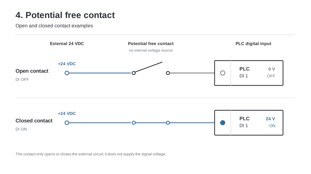
The voltage used to detect the contact normally comes from the controller or from an external circuit.
Example: pressure switch
A differential pressure switch may contain nothing more than a mechanical contact.
The BMS controller supplies the electrical detection circuit.
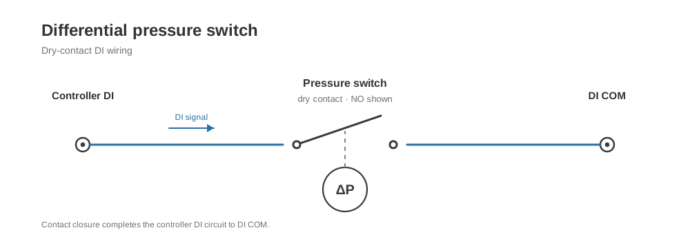
The pressure switch itself does not need to generate a 24 V signal.
It simply changes between open and closed.
Typical dry contact devices
Dry contacts are commonly found on:
- Pressure switches
- Flow switches
- Thermostats
- Fire alarm relays
- Pump fault relays
- Fan run relays
- VFD relay outputs
- Boiler alarm contacts
- Chiller alarm contacts
- Access control interfaces
- Safety relays
- Auxiliary contacts on contactors
5. Dry Contact Does Not Mean Digital Input
A dry contact is an electrical interface, not an I/O category.
A dry contact can be connected to a Digital Input:
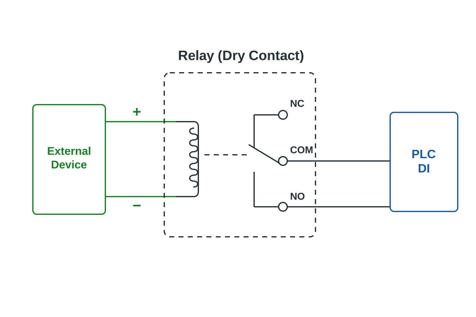
A controller can also provide a dry contact as a Digital Output:
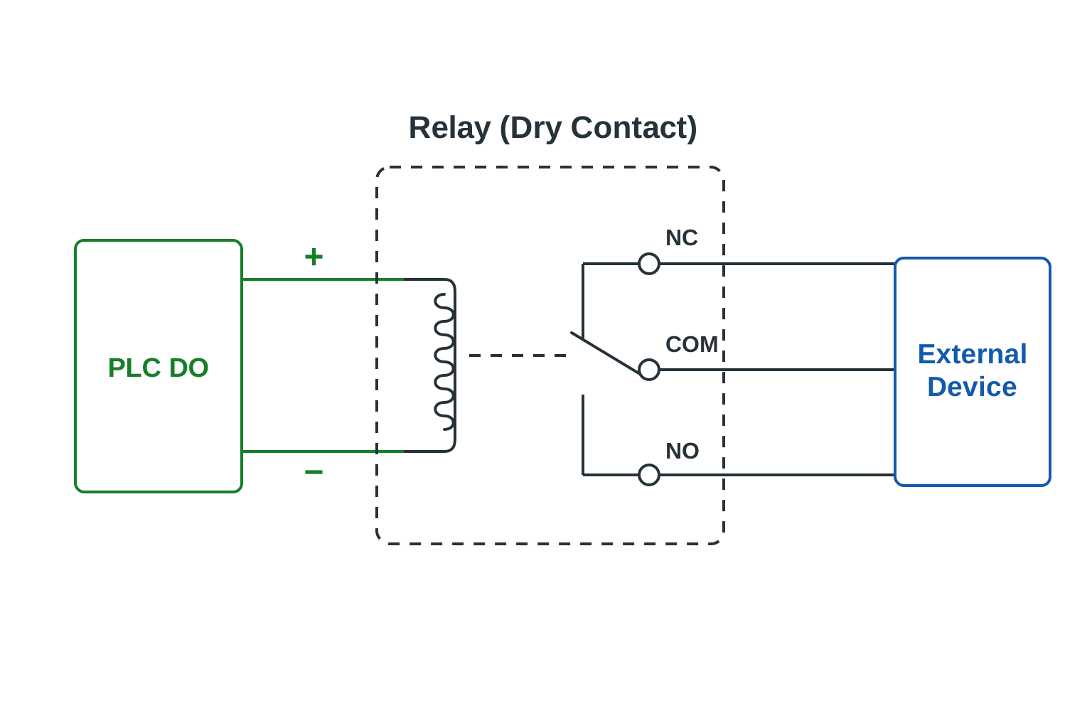
This is an important distinction.
A controller specification might say:
| I/O Type | Count |
|---|---|
| DI | 8 |
| Relay DO | 6 |
| AI | 4 |
| AO | 4 |
The relay Digital Outputs may provide potential free contacts.
6. Wet Contacts
A wet contact generally refers to a digital signal where voltage is already present on the signal.
Instead of simply closing a passive contact, the field device actively sends an electrical voltage.
For example:
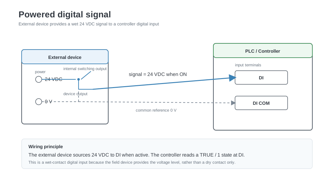
The controller may interpret:
| Voltage | State |
|---|---|
| 0 V | OFF |
| 24 V | ON |
The exact voltage thresholds depend on the controller.
Dry contact compared with wet contact
Dry contact
Field device acts as a switch.

No voltage is intentionally supplied by the contact itself.
Wet contact
Field device supplies an electrical signal.

For example:

0 V = inactive
24 V = active
The term wet contact is used less consistently than dry contact, so the electrical documentation should always be checked.
7. Normally Open and Normally Closed Contacts
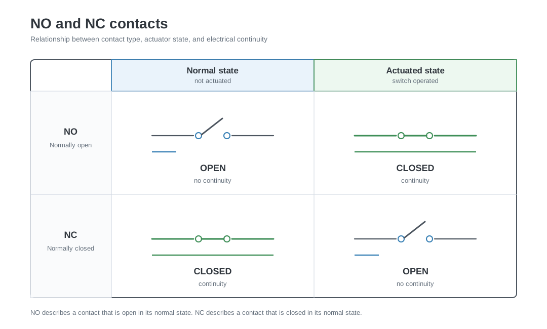
Relay contacts and mechanical switches are commonly described as:
- NO: Normally Open
- NC: Normally Closed
The word normally refers to the contact state when the device is in its normal unactuated or de energised condition.
Normally Open
A Normally Open contact is open in its normal state.
Example:
A fan run relay may close when the fan starts.
| Fan state | Contact state |
|---|---|
| Fan stopped | Contact open |
| Fan running | Contact closed |
Normally Closed
A Normally Closed contact is closed in its normal state.
Example:
A fan run relay may open when the fan starts.
| Fan state | Contact state |
|---|---|
| Fan stopped | Contact closed |
| Fan running | Contact open |
A Normally Closed contact can be useful for safety related monitoring because a broken wire can sometimes create the same electrical state as an alarm.
Whether this behaviour is desirable depends on the application and control philosophy.
8. NO and NC Do Not Define the Software Meaning
A closed contact does not automatically mean TRUE, RUNNING, or ALARM.
The controller software decides what the electrical state means.
For example:
| Contact state | System state |
|---|---|
| Closed contact | Normal |
| Open contact | Alarm |
Another installation could use:
| Contact state | System state |
|---|---|
| Open contact | Normal |
| Closed contact | Alarm |
The input can also be inverted in software.
This is why commissioning requires verification of both:
- The electrical contact state
- The software interpretation
9. COM and Common Terminals
Many I/O modules contain a terminal labelled:
COM
C
Common
GND
0V
M
G0
These labels do not always mean exactly the same thing.
A common terminal provides an electrical reference or shared connection for one or more I/O channels.
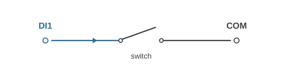
A simple Digital Input circuit could be:
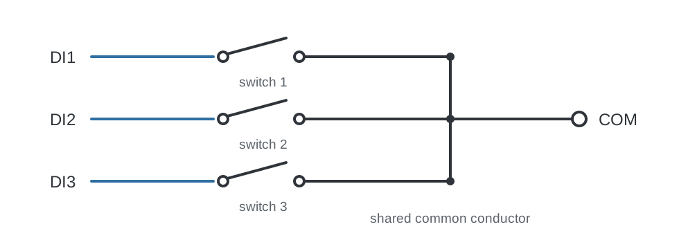
Several inputs might share one common:
The exact internal circuit depends on the controller.
Some commons are connected internally.
Some are grouped.
Some are galvanically isolated from each other.
Some may be connected to 0 V.
Some may expect a positive supply.
Always verify the terminal diagram before wiring.
10. Shared Commons
A controller may group several I/O channels around one shared common terminal.
For example:
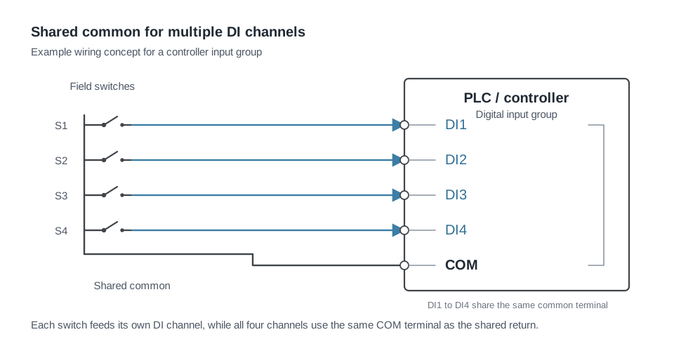
Those four inputs may share the same internal reference.
This can influence how external equipment is connected.
Shared commons are especially important when combining:
- Different power supplies
- Different control panels
- Different voltage references
- Devices with grounded outputs
- Devices with isolated outputs
Connecting two electrical systems together through a shared common can create unexpected current paths.
11. Digital Outputs
A Digital Output, or DO, allows the controller to command something with two states.
Typical examples include:
- Pump start
- Fan start
- Boiler enable
- Chiller enable
- Lighting enable
- Alarm buzzer
- Solenoid valve
- Relay coil
- Contactor coil
- Electric heater stage
- Damper open command
- Damper close command
At the software level:
| Value | Output state |
|---|---|
| FALSE | Output inactive |
| TRUE | Output active |
The electrical behaviour depends on the output hardware.
The three common output technologies are:
- Relay
- Transistor
- Triac
12. Relay Outputs
A relay output contains an electrically operated switch.
A common relay arrangement contains:
COM
NO
NC
Where:
| Terminal | Meaning |
|---|---|
| COM | Common contact |
| NO | Normally Open |
| NC | Normally Closed |
When the relay is inactive:
COM connected to NC
COM disconnected from NO
When the relay activates:
COM connected to NO
COM disconnected from NC
A relay output may be potential free
This means the controller switches the contacts but does not intentionally provide the voltage being switched.
For example:
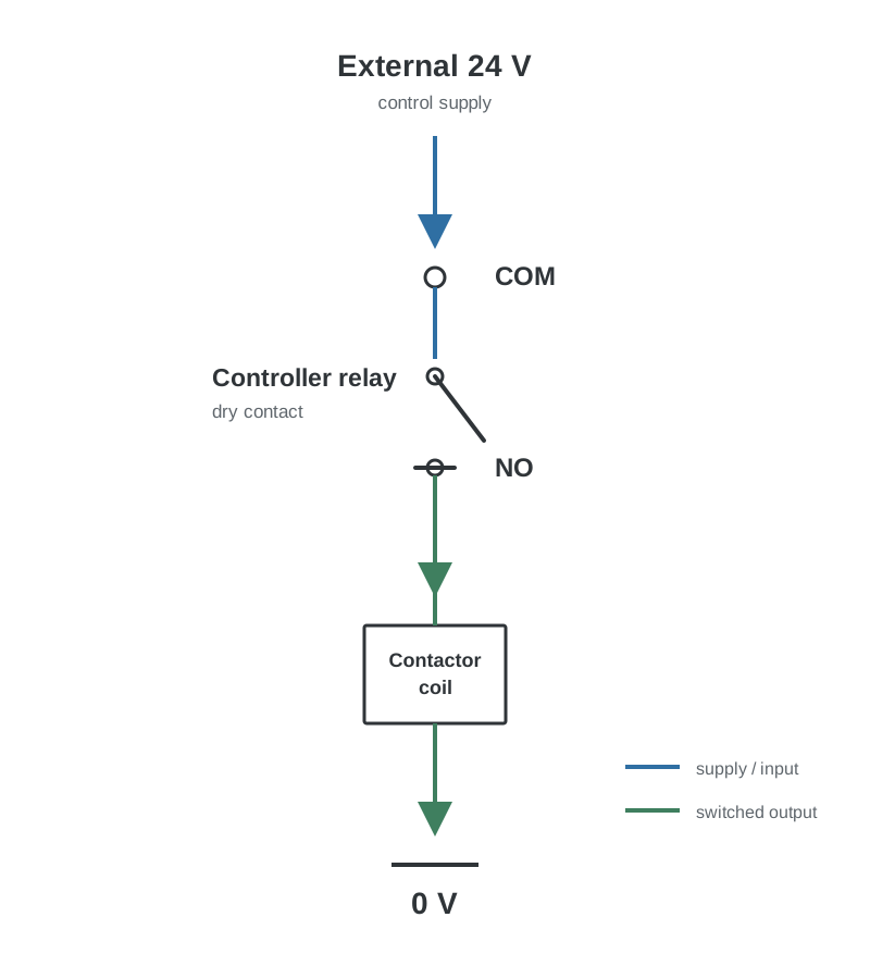
The relay acts as a switch in an external circuit.
13. A Digital Output Usually Does Not Power the Load Directly
A controller output labelled “pump start” does not usually supply power to the pump motor.
The control chain is more commonly:
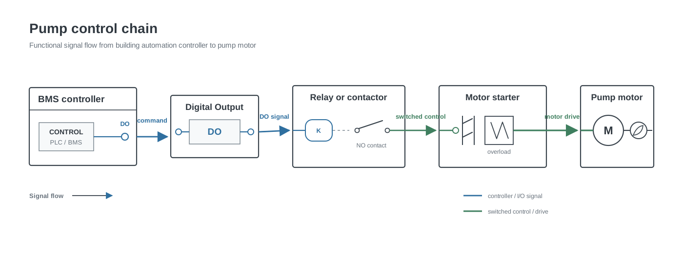
For larger equipment the DO may simply provide an enable signal to:
- A VFD
- A motor starter
- A packaged control panel
- A boiler controller
- A chiller controller
The equipment then handles the high power switching.
14. Relay Contact Ratings
Relay outputs have electrical limits.
Important specifications can include:
- Maximum voltage
- Maximum current
- AC rating
- DC rating
- Resistive load rating
- Inductive load rating
- Minimum switching current
- Mechanical lifetime
- Electrical lifetime
A relay rated for a certain current with a resistive load may support a lower current when switching an inductive load.
Examples of inductive loads include:
- Relay coils
- Contactors
- Solenoids
- Motors
Always check the device documentation.
15. Interposing Relays
An interposing relay is an additional relay installed between the controller and the field equipment.
For example:
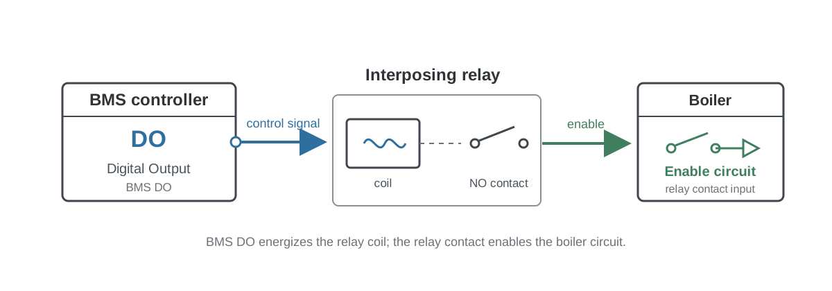
Interposing relays can provide:
- Electrical separation
- Different voltage switching
- Higher contact ratings
- Easier replacement
- Additional contacts
- Clear separation between BMS and third party equipment
They are common in control panels.
16. Transistor Outputs
A transistor output electronically switches a DC circuit.
Unlike a mechanical relay, a transistor has no moving contacts.
Typical characteristics include:
- Fast switching
- Long switching life
- DC operation
- Defined polarity
- Limited output current
Transistor outputs are often described as:
- PNP
- NPN
- Sourcing
- Sinking
- Open collector
- Open drain
The exact terminology depends on the electronics used.
17. PNP and NPN
PNP and NPN terminology is very common in industrial sensors and PLC systems.
A simplified way to understand them is:
PNP
A PNP output typically switches the positive voltage to the input.
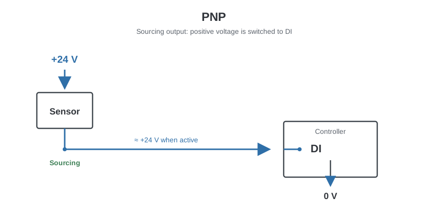
When active, the sensor sends approximately +24 V toward the controller input.
PNP is commonly described as sourcing.
NPN
An NPN output typically switches the signal toward 0 V.
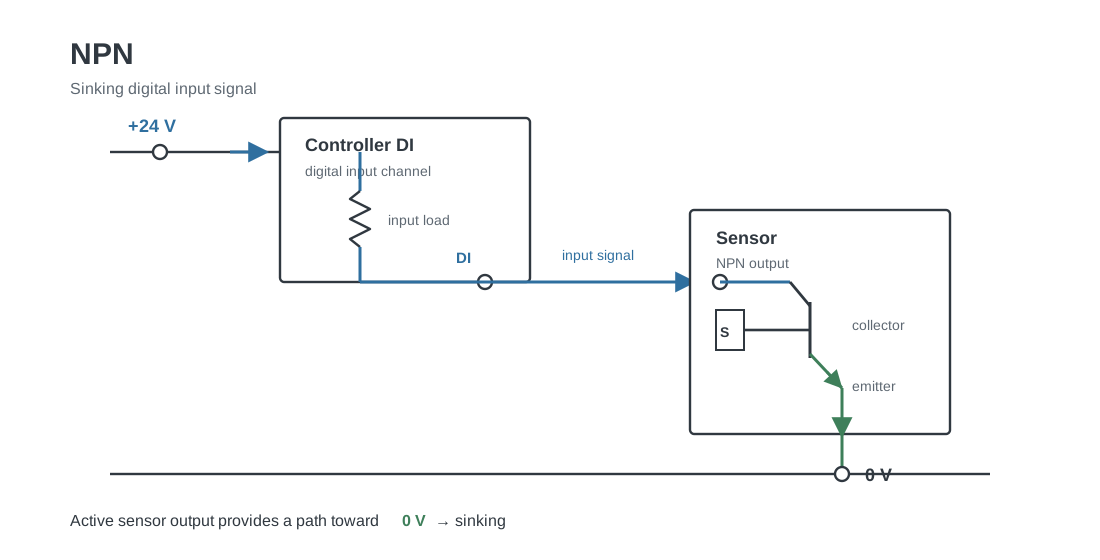
When active, the sensor provides a path toward 0 V.
NPN is commonly described as sinking.
18. Sourcing and Sinking
These terms describe the direction of conventional current flow in DC circuits.
A sourcing device supplies current.
A sinking device provides the return path for current.
A working circuit normally needs one side to source current and the other side to sink it.
For example:
| Component | I/O behavior |
|---|---|
| PNP sensor | Sourcing output |
| PLC input | Sinking input |
Or:
PLC sourcing output
        │
        ▼
Sinking load
This is why a PNP sensor cannot automatically be connected to every Digital Input.
The electrical input circuit must be compatible.
19. Triac Outputs
A triac output is an electronic output commonly used for switching AC loads.
Triacs are often found in HVAC controllers because many actuators and relays operate on 24 VAC.
Typical applications include:
- 24 VAC valve actuators
- 24 VAC damper actuators
- Relay coils
- Small HVAC control loads
Unlike a relay, a triac uses semiconductor switching.
Important characteristics can include:
- AC operation
- Leakage current while OFF
- Minimum load requirements
- Maximum current
- Shared common terminals
A triac output should never be assumed to behave like a potential free relay contact.
20. Digital Input Debouncing
Mechanical contacts do not always change state perfectly.
When a switch closes, the contacts can physically bounce for a very short time.
The electrical signal can briefly look like:
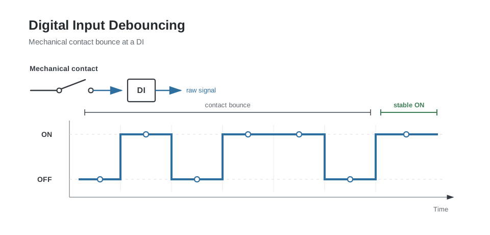
instead of one clean transition.
Controllers can use debouncing or filtering so the state must remain stable for a certain period before it is accepted.
In building automation the same principle is also useful for unstable status signals.
For example:
Filter alarm must remain active for 5 seconds
before generating an alarm.
21. Analog Inputs
An Analog Input, or AI, measures a continuously varying quantity.
Typical BMS measurements include:
- Temperature
- Pressure
- Differential pressure
- Humidity
- CO₂ concentration
- Air quality
- Water flow
- Air flow
- Light level
- Tank level
- Valve feedback
- Damper feedback
- Electrical power measurements
Common electrical signal types include:
- Resistance
- 0–10 V
- 2–10 V
- 0–20 mA
- 4–20 mA
22. Resistance Inputs
Temperature sensors often change resistance as temperature changes.
Common examples include:
- NTC10k
- NTC20k
- PT100
- PT1000
- Ni1000
The controller measures the resistance and converts it into temperature.
23. NTC Temperature Sensors
NTC means:
Negative Temperature Coefficient
The resistance decreases as temperature increases.
An NTC10k sensor has a nominal resistance of approximately 10 kΩ at its specified reference temperature, commonly 25 °C depending on the sensor specification.
Conceptually:
| Temperature | Resistance |
|---|---|
| Low temperature | Higher resistance |
| High temperature | Lower resistance |
The relationship is nonlinear.
This means that:
5 kΩ
does not simply represent half the temperature of:
10 kΩ
The controller needs the correct NTC characteristic curve.
NTC curves matter
Two sensors can both be called NTC10k while using different resistance curves.
Always verify:
- Nominal resistance
- Reference temperature
- Beta value or sensor curve
- Controller sensor type configuration
Selecting the wrong NTC curve can produce a believable but incorrect temperature.
If you are identifying an unknown passive sensor from a resistance measurement, use the temperature sensor identifier and resistance converter.
24. PT100 and PT1000
PT100 and PT1000 sensors are platinum resistance temperature detectors.
Their nominal resistance at 0 °C is approximately:
| Sensor | Resistance |
|---|---|
| PT100 | 100 Ω |
| PT1000 | 1000 Ω |
Unlike an NTC sensor, platinum RTD resistance increases as temperature increases.
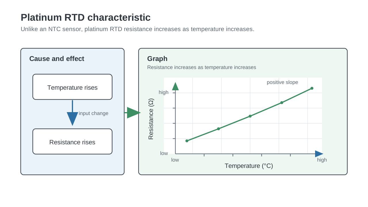
PT1000 is common in HVAC because its higher resistance reduces the relative effect of cable resistance compared with PT100.
25. 2 Wire, 3 Wire, and 4 Wire Resistance Measurement
Resistance sensors can be measured with different wiring arrangements.
2 wire
The measured resistance includes:
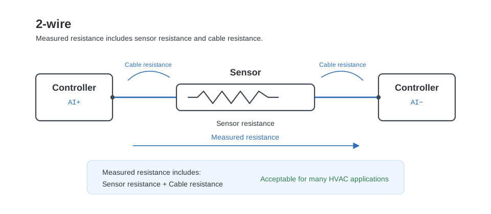
For many HVAC applications this is acceptable.
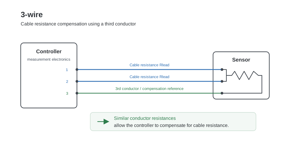
3 wire
A third conductor allows the measurement electronics to compensate for cable resistance, assuming the conductor resistances are similar.
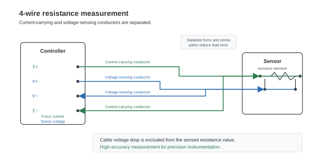
4 wire
A four wire measurement can provide very accurate resistance measurement because current carrying and voltage sensing conductors are separated.
Four wire measurement is common in precision instrumentation.
26. Voltage Inputs
A common BMS analog signal is:
0–10 V
Example:
A pressure transmitter may be configured as:
| Voltage | Pressure |
|---|---|
| 0 V | 0 Pa |
| 10 V | 1000 Pa |
Therefore:
| Voltage | Pressure |
|---|---|
| 2.5 V | 250 Pa |
| 5.0 V | 500 Pa |
| 7.5 V | 750 Pa |
| 10 V | 1000 Pa |
This conversion is called scaling.
27. Analog Scaling
The general scaling formula is:
$$ \begin{aligned} \text{Engineering value} &= \text{Engineering minimum} \ &\quad + \frac{ \text{Input value} - \text{Input minimum} }{ \text{Input maximum} - \text{Input minimum} } \ &\quad \times \left( \text{Engineering maximum} - \text{Engineering minimum} \right) \end{aligned} $$
For a 0–10 V pressure sensor measuring 0–1000 Pa:
| Parameter | Value |
|---|---|
| Input minimum | 0 V |
| Input maximum | 10 V |
| Engineering minimum | 0 Pa |
| Engineering maximum | 1000 Pa |
At an input voltage of 6.37 V:
$$ \begin{aligned} \text{Engineering value} &= 0 + \frac{6.37 - 0}{10 - 0} \times (1000 - 0) \ &= \frac{6.37}{10} \times 1000 \ &= 637\ \text{Pa} \end{aligned} $$
Therefore:
$$ 6.37\ \text{V} = 637\ \text{Pa} $$
28. 2–10 V Signals
Some field devices use:
2–10 V
instead of:
0–10 V
For a 0–100 % signal:
| Voltage | Output |
|---|---|
| 2 V | 0 % |
| 6 V | 50 % |
| 10 V | 100 % |
The 2 V offset can provide additional diagnostic possibilities.
A signal significantly below 2 V may indicate a wiring or device problem, depending on the equipment.
29. Signal Common for 0–10 V
A 0–10 V signal is measured relative to a reference.
A typical connection is:
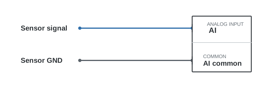
The controller evaluates Voltage between AI and common. Thus the signal reference matters.
For example, a sensor could output 7 V relative to its own ground while the controller measures a different voltage if the two reference potentials are different.
This is why 0–10 V systems require careful attention to:
- Signal common
- Power supply common
- Grounding
- Isolation
- Cable routing
30. Current Inputs
Another very common analog signal is:
4–20 mA
Current loops are widely used in industrial systems.
A typical scaling could be:
| Current | Pressure |
|---|---|
| 4 mA | 0 Pa |
| 20 mA | 1000 Pa |
Then:
12 mA = 500 Pa
because 12 mA is halfway between 4 mA and 20 mA.
31. Why 4–20 mA Starts at 4 mA
The 4 mA starting point is often called a live zero.
The normal measurement range is:
4 mA to 20 mA
This leaves room below 4 mA for fault detection.
For example, a system may distinguish between:
| Current | Meaning |
|---|---|
| 4 mA | Valid minimum measurement |
| 0 mA | Possible broken wire or power loss |
The exact fault thresholds depend on the transmitter and input module.
32. Scaling a 4–20 mA Signal
For a 0–1000 Pa pressure sensor:
4 mA  = 0 Pa
20 mA = 1000 Pa
The usable current span is:
20 - 4 = 16 mA
At 12 mA:
12 - 4 = 8 mA
8 mA is half of the 16 mA span.
Therefore:
12 mA = 500 Pa
Another example:
Input = 16 mA
First calculate position inside the current range:
(16 - 4) / 16 = 0.75
Then scale to engineering units:
0.75 × 1000 Pa = 750 Pa
33. Current Loop Wiring
A current loop must form a complete electrical circuit.
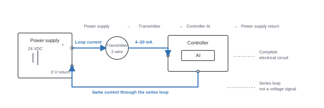
The same current flows through the series loop.
This is fundamentally different from a voltage signal.
34. 2 Wire Loop Powered Transmitters
A 2 wire transmitter commonly uses the same two conductors for both:
- Device power
- Measurement signal
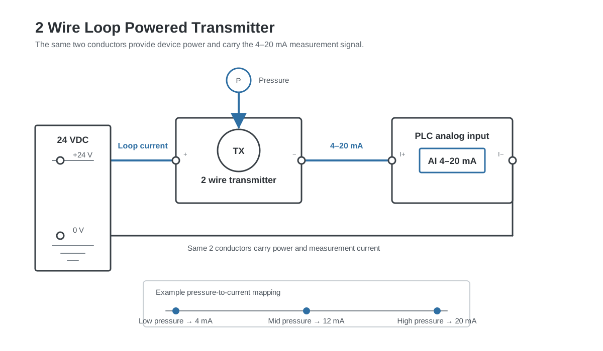
The transmitter regulates the loop current according to the measured value.
For example:
| Pressure | Current |
|---|---|
| Low pressure | 4 mA |
| Mid pressure | 12 mA |
| High pressure | 20 mA |
35. 3 Wire Transmitters
A 3 wire transmitter commonly has separate connections for:
Power +
Power -
Signal
For example:
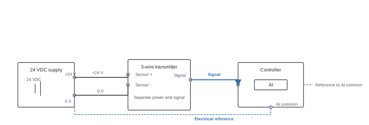
The signal still requires the correct electrical reference.
36. 4 Wire Transmitters
A 4 wire transmitter may have separate power and signal circuits.
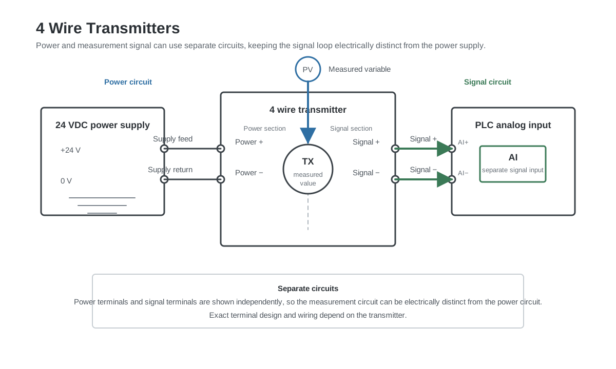
This can make the measurement circuit electrically distinct from the power circuit.
The exact wiring depends on the transmitter.
37. Active and Passive Analog Signals
The words active and passive are commonly used when discussing analog current loops.
Unfortunately, terminology can vary between manufacturers.
The important practical question is:
Which device provides the loop power?
For a 4–20 mA circuit, one device must provide the electrical energy required to drive the current through the loop.
Possible arrangements include:
Controller powers the loop
or:
External power supply powers the loop
or:
Transmitter has its own power source
Before connecting a current loop, identify:
- Which side supplies voltage
- Which side measures current
- Input polarity
- Maximum loop voltage
- Maximum input resistance
38. Analog Outputs
An Analog Output, or AO, sends a continuously variable command from the controller.
Typical BMS applications include:
- Heating valve position
- Cooling valve position
- Damper position
- VFD speed reference
- Fan speed
- Pump speed
- Electric heater demand
- Humidifier demand
- Pressure setpoint
- Remote equipment setpoint
The most common BMS analog output signal is:
0–10 V
39. 0–10 V Output Control
A typical valve actuator may use:
0 V  = 0 %
5 V  = 50 %
10 V = 100 %
If the controller calculates a heating demand of:
72 %
the analog output could send approximately:
7.2 V
to the actuator.
40. Direct Acting and Reverse Acting
The relationship between signal and physical position can be configured differently.
Direct acting
0 V  = closed
10 V = open
Reverse acting
0 V  = open
10 V = closed
The same idea can apply to:
- Valves
- Dampers
- VFD references
- Heating controllers
Correct commissioning requires checking the actual physical result.
A software value of 100 % should never simply be assumed to mean physically open.
41. 2–10 V Analog Outputs
Some actuators use:
2–10 V
For example:
2 V  = 0 %
6 V  = 50 %
10 V = 100 %
This can provide a useful distinction between minimum command and a missing signal.
The behaviour below 2 V depends on the actuator.
42. 4–20 mA Analog Outputs
Some controllers can also generate current outputs.
For example:
4 mA  = 0 %
12 mA = 50 %
20 mA = 100 %
Current outputs can be useful over longer cable distances and in electrically noisy environments.
Compatibility with the receiving device must be checked.
43. Analog Output Feedback
A command signal does not prove that a physical device reached the requested position.
For example:
AO command = 80 %
The valve could still be:
- Stuck
- Unpowered
- Manually overridden
- Mechanically disconnected
- Wired incorrectly
Some actuators provide a feedback signal.
For example:
AO1 = valve command
AI3 = valve position feedback
The controller can compare:
Commanded position
versus
Actual position
This makes fault detection much more reliable.
44. Floating or 3 Point Control
Some actuators do not use a proportional analog signal.
Instead they have two digital commands:
OPEN
CLOSE
This is called:
- Floating control
- 3 point control
- Three position control
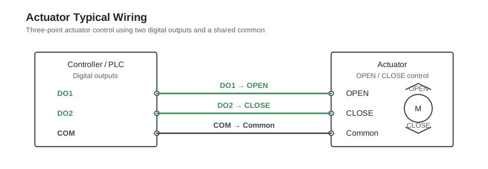
The controller drives the actuator in one direction for a calculated period.
For example:
| OPEN | CLOSE | Actuator action |
|---|---|---|
| ON | OFF | Moves open |
| OFF | ON | Moves closed |
| OFF | OFF | Stops |
This is common with valve and damper actuators.
Although the final position is analog in nature, the controller uses Digital Outputs to move the actuator.
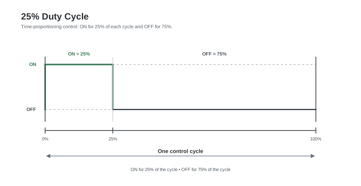
45. PWM Outputs
PWM means Pulse Width Modulation.
Instead of generating a continuously variable voltage, the controller rapidly switches an output ON and OFF.
The percentage of time the output remains ON determines the effective command.
For example:
25 % demand
could produce:
PWM is used by some:
- Thermal actuators
- Heating controllers
- Solid state relays
- Fan controllers
PWM should only be used with equipment designed for it.
46. Input and Output Impedance
Analog voltage circuits have electrical loading.
A controller Analog Input has an input impedance.
An Analog Output has a limited ability to supply current.
Consider a 0–10 V output connected to several devices:
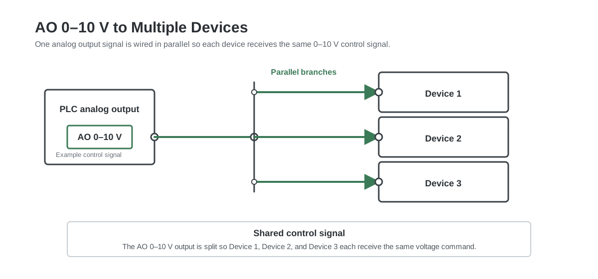
Each connected device loads the output.
If the total load becomes too large, the output voltage may become inaccurate or the output may be overloaded.
This is why controller and actuator documentation includes specifications such as:
Minimum load resistance
Maximum output current
Input impedance
47. Pull Up and Pull Down Resistors
Digital electronic circuits sometimes use pull up or pull down resistors to establish a defined state when no external device is actively driving the input.
A pull up resistor biases the signal toward a positive voltage.
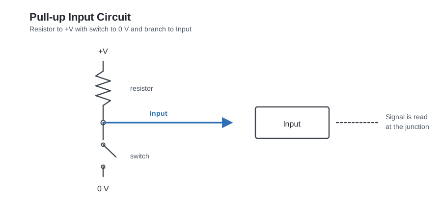
With the switch open, the resistor keeps the input high.
With the switch closed, the input is pulled low.
A pull down resistor works in the opposite direction.
Most BMS technicians do not need to design these circuits, but understanding the principle is useful when reading controller schematics or connecting open collector outputs.
48. Galvanic Isolation
Galvanic isolation means two circuits can exchange information without having a direct conductive electrical connection between them.
Isolation can be implemented using components such as:
- Optocouplers
- Transformers
- Isolation amplifiers
- Relays
Isolation can help with:
- Ground potential differences
- Electrical noise
- Equipment protection
- Separation between systems
- Preventing unwanted current paths
A specification might say:
Galvanically isolated inputs
or:
Channel to bus isolation
The exact isolation arrangement matters.
For example, channels may be isolated from the controller CPU while still sharing a common with each other.
49. Ground Loops
A ground loop can occur when two devices are electrically connected through more than one ground or reference path.
For example:
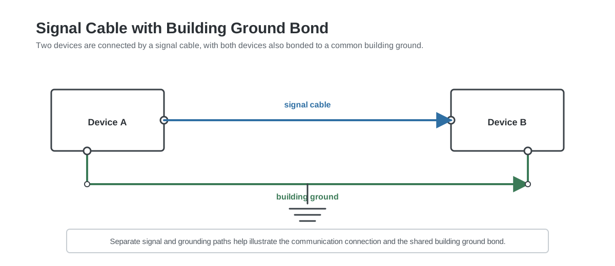
If the two ground points are at slightly different electrical potentials, unwanted current can flow.
This can affect analog measurements.
Symptoms can include:
- Temperature readings that shift when equipment starts
- Unstable pressure readings
- Incorrect 0–10 V values
- Noise on sensor signals
- Different readings depending on which devices are powered
Good system design considers grounding, signal reference, isolation, shielding, and cable routing together.
50. Cable Shielding
Analog signals can be affected by electromagnetic interference.
Sources of interference can include:
- Variable frequency drives
- Motors
- Contactors
- High current cables
- Switching power supplies
- Radio equipment
Shielded cable may be used for sensitive analog signals.
The shield connection method depends on the equipment and installation design.
A cable shield should not automatically be connected at both ends without considering the grounding strategy.
Follow the field device, controller, and project electrical documentation.
51. AC and DC Control Signals
BMS equipment commonly uses:
24 VAC
24 VDC
230 VAC
0–10 VDC
4–20 mA
These are not interchangeable.
For example:
A 24 VAC actuator supply does not mean its 0–10 V control input should receive AC.
The actuator may use:
24 VAC power
0–10 VDC control signal
at the same time.
Always identify each terminal individually.
52. G, G0, 24 V, 0 V, and Common
HVAC devices often use terminal names such as:
G
G0
24V
0V
COM
M
GND
A common convention is:
G  = supply
G0 = supply common
but conventions vary.
On a 24 VAC actuator, G and G0 may refer to AC supply conductors.
On another device, 24 V and 0 V may represent DC.
Never assume terminal meaning from the name alone.
53. Raw Controller Values
Controllers often convert physical electrical signals into internal numerical values.
For example, a 0–10 V input could internally appear as:
0      = 0 V
32767  = 10 V
Then:
16384 ≈ 5 V
The controller software may scale this further:
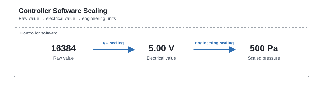
The exact raw range depends on the hardware.
Other systems may use values such as:
Range:
0–1000
0–4095
0–10000
0–27648
0–32767
The principle is the same.
Raw electrical value
       │
       ▼
Electrical engineering value
       │
       ▼
Physical engineering value
54. Resolution
Analog conversion has finite resolution.
For example, an analog input cannot represent an infinite number of voltage values.
It divides the measurement range into discrete steps.
Higher resolution allows smaller changes to be represented.
For normal HVAC measurements, other factors such as sensor accuracy, installation, calibration, and electrical noise can be equally important.
55. Analog Filtering
Real sensor values often fluctuate.
A pressure measurement could look like:
498 Pa
503 Pa
496 Pa
507 Pa
501 Pa
A controller can apply filtering to make the control value smoother.
For example:
| Raw value | Filtered value |
|---|---|
| 498 Pa | 498 Pa |
| 503 Pa | 499 Pa |
| 496 Pa | 499 Pa |
| 507 Pa | 501 Pa |
| 501 Pa | 501 Pa |
Filtering can improve stability.
Too much filtering creates a slow response.
The correct balance depends on the process.
56. Sensor Failure Detection
A good control program considers what happens when an input fails.
Possible failures include:
- Broken wire
- Short circuit
- Loss of sensor power
- Incorrect signal
- Sensor outside valid range
- Frozen value
- Implausible measurement
For example, a room temperature sensor could be considered faulty if it reports:
-80 °C
or:
180 °C
even if the electrical input technically produces a number.
57. Open Circuit Behaviour
Different signal types behave differently when a wire breaks.
Dry contact
A broken wire usually appears electrically similar to an open contact. Open contact and broken wire can therefore produce the same input state. This is one reason Normally Closed alarm circuits are sometimes used.
Resistance sensor
A broken sensor wire often results in extremely high resistance.
The controller may detect:
Open circuit
Sensor fault
Out of range
0–10 V
A broken signal wire can produce different behaviour depending on the input electronics.
The measured value may fall toward 0 V, float, or become unstable.
4–20 mA
A broken loop commonly causes current to fall well below the valid 4–20 mA measurement range.
This provides useful fault detection.
58. Short Circuit Behaviour
A short circuit also produces different symptoms depending on the signal.
For a resistance sensor:
Near 0 Ω
may indicate a short.
For a 0–10 V signal:
Signal shorted to common
may produce approximately:
0 V
For powered digital circuits, a short may cause:
- Fuse operation
- Power supply protection
- Output protection
- Equipment damage if the circuit is not properly protected
59. Fail Safe Operation
Fail safe describes the desired behaviour when control power, communication, or a control signal is lost.
Examples include:
- Heating valve closes
- Cooling valve closes
- Outside air damper closes
- Smoke damper moves to its safety position
- Pump stops
- Alarm relay changes state
Actuators may use:
- Spring return
- Stored energy
- Normally closed mechanical design
- Normally open mechanical design
- Configurable signal loss behaviour
Fail safe behaviour should be defined by the system design and safety requirements.
60. Fail Open and Fail Closed Valves
A valve can be selected to move to a defined position when power is lost.
Fail closed
Power lost
    │
    ▼
Valve closes
Fail open
Power lost
    │
    ▼
Valve opens
The correct choice depends on the application.
For example, freeze protection requirements may lead to a different fail position than normal room temperature control.
61. Feedback Versus Command
A common BMS design contains both command and feedback.
Example:
DO = Fan Start Command
DI = Fan Run Feedback
These signals answer different questions.
DO asks:
Did the BMS tell the fan to start?

DI asks:
Did the fan actually start?
This allows fault logic such as:
Fan command ON
+
No fan feedback after 10 seconds
=
Fan failed to start alarm
The same idea applies to pumps:
Pump start DO
Pump run DI
Pump fault DI
62. Enable, Status, Alarm, and Interlock
These terms are often seen on BMS wiring diagrams.
Enable
A command allowing equipment to operate.
Example:
Boiler Enable
Status
A signal describing the current equipment state.
Example:
Boiler Running
Alarm
A signal indicating a problem.
Example:
Boiler Common Alarm
Interlock
A condition that permits or prevents operation based on another condition.
Example:
Supply fan may start only when fire alarm interlock is healthy.
An interlock can exist in:
- Hardware
- Software
- Both
63. Example: Complete Pump I/O
A typical pump could have:
| I/O | Signal |
|---|---|
| DO1 | Pump Start |
| DI1 | Pump Run |
| DI2 | Pump Fault |
| AI1 | Differential Pressure |
| AO1 | Speed Reference |
The control sequence might be:
1. BMS activates Pump Start.
2. Pump or VFD starts.
3. Pump Run feedback becomes active.
4. BMS controls speed through AO.
5. Differential pressure is measured through AI.
6. Pump Fault generates an alarm if a fault occurs.
This shows how all four I/O types can work together.
64. Example: Complete Air Handling Unit I/O
An AHU can contain dozens of I/O points.
Digital Inputs
Supply fan run
Supply fan fault
Extract fan run
Extract fan fault
Filter alarm
Freeze thermostat
Fire alarm
Damper end switch
Digital Outputs
Supply fan enable
Extract fan enable
Pump start
Electric heater stage
Alarm relay
Analog Inputs
Outdoor temperature
Supply air temperature
Extract air temperature
Room temperature
Supply duct pressure
Extract duct pressure
CO₂
Humidity
Heating valve feedback
Analog Outputs
Heating valve
Cooling valve
Supply fan speed
Extract fan speed
Outside air damper
Return air damper
The I/O points together form the physical connection between the control program and the HVAC system.
65. Typical BMS Signal Examples
| Device | Typical signal | I/O type |
|---|---|---|
| Room temperature sensor | NTC10k | AI |
| Duct temperature sensor | PT1000 | AI |
| Pressure transmitter | 0–10 V | AI |
| Differential pressure transmitter | 4–20 mA | AI |
| Filter pressure switch | Dry contact | DI |
| Fan run relay | Dry contact | DI |
| Fan fault relay | Dry contact | DI |
| Pump enable | Relay contact | DO |
| Heating valve | 0–10 V | AO |
| Cooling valve | 0–10 V | AO |
| VFD speed reference | 0–10 V | AO |
| VFD run command | Dry relay contact | DO |
| VFD run status | Dry relay contact | DI |
| CO₂ transmitter | 0–10 V or 4–20 mA | AI |
| Valve position feedback | 0–10 V | AI |
| 3 point valve actuator | Open and Close commands | 2 × DO |
66. How to Troubleshoot a Digital Input
Suppose the controller shows:
Fan status = OFF
but the fan is clearly running.
A logical troubleshooting sequence is:
Step 1: Check the physical equipment
Confirm that the fan actually runs.
Step 2: Check the source contact
Check whether the VFD, contactor, or relay output changes state.
Step 3: Check the field wiring
Check continuity through the cable.
Step 4: Check the voltage or contact state at the controller
Verify that the expected electrical signal reaches the DI terminal.
Step 5: Check the controller input indication
Many controllers have an LED showing the physical input state.
Step 6: Check software mapping
Confirm that the correct physical input is mapped to the correct software point.
Step 7: Check inversion
Verify whether the point is configured as Normally Open, Normally Closed, direct, or inverted.
Following the signal from the field toward the software usually makes the fault easier to locate.
67. How to Troubleshoot a Digital Output
Suppose:
BMS says Pump Start = ON
but the pump remains stopped.
Work through the control chain:
Software command
      │
      ▼
 Physical DO
      │
      ▼
Relay contact
      │
      ▼
Field wiring
      │
      ▼
Motor starter or VFD
      │
      ▼
    Pump
Check each stage.
Useful questions include:
- Is the software output TRUE?
- Is the physical output LED ON?
- Has the relay changed state?
- Is the expected voltage present?
- Is the external enable circuit healthy?
- Is the VFD in Remote mode?
- Is a safety interlock preventing operation?
- Is the equipment in manual override?
- Is the motor starter healthy?
68. How to Troubleshoot an Analog Input
Suppose the BMS shows:
Duct pressure = 0 Pa
while the fan is running.
Check:
Physical process
      │
      ▼
    Sensor
      │
      ▼
Electrical signal
      │
      ▼
Controller AI
      │
      ▼
   Scaling
      │
      ▼
Software value
For a 0–10 V transmitter:
- Verify transmitter power.
- Measure the voltage between signal and signal common.
- Compare the measured voltage with the expected pressure.
- Check the controller AI configuration.
- Check scaling.
- Check engineering units.
For a 4–20 mA transmitter:
- Verify loop power.
- Measure loop current using the correct measurement method.
- Check polarity.
- Verify input configuration.
- Check scaling.
- Check fault limits.
69. How to Troubleshoot an Analog Output
Suppose:
Valve command = 50 %
but the valve remains closed.
Follow the signal:
Software AO = 50 %
        │
        ▼
 Physical output
        │
        ▼
Approximately 5 V for a 0–10 V signal
        │
        ▼
  Field wiring
        │
        ▼
 Actuator input
        │
        ▼
Mechanical valve position
Check:
- Is the software command correct?
- Is the AO channel configured as 0–10 V?
- Does the controller physically produce approximately 5 V?
- Does the actuator receive the same voltage?
- Does the actuator have power?
- Is the actuator configured for the correct signal type?
- Is the actuator in manual mode?
- Is the actuator mechanically connected to the valve?
- Is the signal direction reversed?
70. Using a Multimeter
A multimeter is one of the most useful tools for BMS commissioning.
Depending on the signal, it can be used to measure:
- Voltage
- Resistance
- Current
- Continuity
Dry contact
Use continuity or resistance measurement on an isolated and safe circuit.
Typical result:
Contact open   → very high resistance
Contact closed → very low resistance
0–10 V
Use DC voltage measurement.
Measure:
Signal
to
Signal common
Resistance sensor
Disconnect or isolate the sensor as required by the equipment documentation before measuring resistance.
Measure across the sensor conductors.
4–20 mA
Current measurement requires the meter to become part of the current path.
This measurement should be performed carefully because incorrect meter connection can interrupt or short the loop.
71. Forcing Outputs During Commissioning
Many BMS controllers allow an output to be manually forced.
For example:
AO = 0 %
AO = 50 %
AO = 100 %
This can be useful for testing:
- Valve movement
- Damper movement
- VFD speed
- Pump start circuits
- Relay operation
A useful analog output test is:
0 %   → measure approximately 0 V
50 %  → measure approximately 5 V
100 % → measure approximately 10 V
for a 0–10 V output.
Manual forcing should be performed with awareness of the physical system.
Unexpected equipment movement can create hazards or damage equipment.
Always return overridden points to normal automatic control after testing.
72. Common I/O Wiring Mistakes
Wrong common
The signal conductor is correct but the reference conductor is connected incorrectly.
Result:
Incorrect or unstable analog reading
Wrong signal type
The controller expects:
4–20 mA
while the transmitter provides:
0–10 V
Result:
Incorrect measurement
Wrong sensor curve
The controller is configured for one NTC10k curve while another NTC10k sensor type is installed.
Result:
Temperature looks plausible but is incorrect
Assuming a relay output provides voltage
A potential free relay output only switches the external circuit.
Result:
Output LED turns ON
but field device receives no voltage
NO and NC reversed
The wiring uses the opposite contact from the intended design.
Result:
Alarm active during normal operation
Wrong PNP or NPN compatibility
The sensor output and controller input use incompatible current direction.
Result:
Input never changes
Missing transmitter power
The analog signal wiring is present but the sensor has no supply voltage.
Result:
0 V
0 mA
or invalid measurement
Incorrect 4–20 mA loop wiring
The loop is not electrically complete.
Result:
No current flows
Too much analog output loading
Several devices are connected to one voltage output and exceed its allowed load.
Result:
Output voltage becomes inaccurate
73. Commissioning an I/O Point
Every important I/O point should be tested from the physical device through to the BMS software.
A practical process is:
Digital Input
1. Physically activate the device.
2. Confirm the contact changes.
3. Confirm the controller input changes.
4. Confirm the BMS software changes.
5. Confirm the correct text is displayed.
6. Test alarm logic if applicable.
Digital Output
1. Command the output.
2. Confirm the controller output activates.
3. Confirm the field voltage or contact state.
4. Confirm the equipment responds.
5. Confirm feedback is received.
Analog Input
1. Measure the physical process.
2. Measure the electrical signal.
3. Compare with the controller value.
4. Verify scaling.
5. Verify engineering units.
6. Check reasonable minimum and maximum values.
Analog Output
1. Force 0 %.
2. Measure the electrical output.
3. Observe the physical device.
4. Force 50 %.
5. Repeat the measurement.
6. Force 100 %.
7. Confirm full mechanical movement.
8. Return the point to automatic control.
74. I/O Point Naming
Clear point names make BMS systems easier to understand.
Good names describe both the equipment and the signal.
For example:
AHU01_SupplyFan_Run
AHU01_SupplyFan_Fault
AHU01_SupplyFan_Start
AHU01_SupplyFan_Speed
AHU01_SupplyAir_Temp
AHU01_SupplyPressure
AHU01_HeatingValve_Cmd
AHU01_HeatingValve_Fb
Avoid vague names such as:
Input1
Output3
SensorA
Relay2
Clear naming greatly improves commissioning and maintenance.
75. I/O Documentation
A useful I/O list normally includes fields such as:
| Field | Example |
|---|---|
| Point name | AHU01 Supply Air Temperature |
| I/O type | AI |
| Signal type | PT1000 |
| Controller | AHU01 Controller |
| Terminal | AI3 |
| Engineering unit | °C |
| Minimum | -40 |
| Maximum | 100 |
| Alarm limits | -20 / 60 |
| Description | Supply air temperature sensor |
For a digital point:
| Field | Example |
|---|---|
| Point name | AHU01 Supply Fan Run |
| I/O type | DI |
| Signal | Dry contact |
| Contact | NO |
| Controller | AHU01 Controller |
| Terminal | DI2 |
| Normal state | OFF |
| Active state | Running |
Good documentation saves considerable time during installation and troubleshooting.
76. Choosing Between Signal Types
Different signal types have different strengths.
Dry contact
Useful for:
- Simple status
- Alarm
- Enable
- Interlock
Advantages:
- Simple
- Easy to understand
- Easy to test
0–10 V
Useful for:
- HVAC actuators
- Short to moderate analog signal runs
- Pressure and environmental transmitters
Advantages:
- Simple measurement with a multimeter
- Very common in HVAC
4–20 mA
Useful for:
- Industrial transmitters
- Longer cable runs
- Environments with electrical noise
- Applications where open loop detection is useful
Advantages:
- Live zero
- Current signal is less sensitive to voltage drop in the signal conductors
Resistance sensor
Useful for:
- Temperature measurement
Advantages:
- Simple sensor
- No separate transmitter required in many applications
77. Quick Reference
DI
Direction: Into controller
Data:      Two state
Examples:  Run, fault, alarm, occupancy
Signals:   Dry contact, 24 VDC, PNP, NPN
DO
Direction: Out of controller
Data:      Two state
Examples:  Start, stop, enable
Hardware:  Relay, transistor, triac
AI
Direction: Into controller
Data:      Variable
Examples:  Temperature, pressure, CO₂
Signals:   Resistance, 0–10 V, 4–20 mA
AO
Direction: Out of controller
Data:      Variable
Examples:  Valve, damper, VFD speed
Signals:   0–10 V, 2–10 V, 4–20 mA
78. BMS I/O Terminology Cheat Sheet
| Term | Meaning |
|---|---|
| DI | Digital Input |
| DO | Digital Output |
| AI | Analog Input |
| AO | Analog Output |
| Dry contact | Contact that switches a circuit without intentionally supplying its own voltage |
| Potential free | Another name for a dry contact |
| Volt free | Another name for a dry contact |
| Wet contact | Digital signal where voltage is supplied by the source |
| NO | Normally Open |
| NC | Normally Closed |
| COM | Common connection |
| Relay | Electrically controlled switch |
| PNP | Typically a sourcing transistor output |
| NPN | Typically a sinking transistor output |
| Sourcing | Supplying current to a circuit |
| Sinking | Providing the return path for current |
| 0–10 V | Common analog voltage signal |
| 2–10 V | Analog voltage signal with an offset |
| 4–20 mA | Common analog current loop |
| Live zero | Nonzero minimum signal used to help distinguish a valid minimum from some fault conditions |
| NTC | Negative Temperature Coefficient thermistor |
| PT1000 | Platinum resistance temperature sensor |
| Loop powered | Device powered through its current loop |
| Galvanic isolation | Electrical separation between circuits |
| Floating control | Open and Close actuator control using two digital outputs |
| PWM | Pulse Width Modulation |
| Feedback | Signal reporting the actual equipment state or position |
| Enable | Command allowing equipment to operate |
| Interlock | Condition that permits or prevents operation |
| Fail safe | Defined behaviour following loss of power, signal, or another required condition |
79. A Practical Way to Think About Any Unknown I/O Point
When you encounter an unfamiliar I/O connection, answer these questions in order.
1. Is it an input or an output?
Field → Controller = Input
Controller → Field = Output
2. Is it digital or analog?
Two states       = Digital
Variable quantity = Analog
3. What is the electrical signal?
Examples:
Dry contact
24 VDC
24 VAC
0–10 V
2–10 V
4–20 mA
NTC10k
PT1000
4. Who supplies the voltage or current?
Determine whether power comes from:
Controller
Field device
External power supply
Current loop
5. What is the common or reference?
Identify:
COM
0 V
G0
Signal -
and confirm how it is electrically connected.
6. What does the signal mean?
For example:
Contact closed = Fan Running
or:
4 mA  = 0 Pa
20 mA = 1000 Pa
7. What happens during a failure?
Consider:
Broken wire
Loss of power
Short circuit
Sensor failure
Loss of communication
If you can answer these seven questions, most BMS I/O circuits become much easier to understand.
80. Final Summary
The four fundamental BMS I/O types are simple:
DI = Digital information coming in
DO = Digital command going out
AI = Analog measurement coming in
AO = Analog command going out
The complexity comes from the electrical methods used to carry those signals.
A Digital Input might receive a dry contact, a 24 V signal, a PNP output, or an NPN output.
A Digital Output might use a relay, transistor, or triac.
An Analog Input might measure an NTC sensor, PT1000 sensor, 0–10 V transmitter, or 4–20 mA current loop.
An Analog Output might control a valve, damper, VFD, or heater using 0–10 V, 2–10 V, or 4–20 mA.
Once you understand the difference between the logical I/O type, the electrical signal, and the physical field device, reading BMS wiring diagrams and troubleshooting control systems becomes much more systematic.