
Building Automation Sensors and Transmitters
A building automation system can display thousands of measurements: room temperature, supply air temperature, duct pressure, relative humidity, CO₂ concentration, filter pressure drop, outdoor conditions and many others. On the screen these values often look equally simple. A temperature may be shown as 21.4 °C, a CO₂ concentration as 812 ppm, and a duct pressure as 185 Pa.
The measurement behind each value can be very different. A temperature sensor may be nothing more than a passive platinum resistor connected directly to a controller input. A CO₂ transmitter contains an optical measurement system, electronics, compensation and signal processing before it sends a 0–10 V signal or a digital value to the controller. A differential pressure transmitter converts a tiny pressure difference into an electrical signal, while a VOC sensor may respond to a broad group of gases and calculate an air-quality index instead of measuring one specific compound.
Understanding this measurement chain is useful in design, commissioning and troubleshooting. When a BMS value is wrong, the controller is only one possible cause. The error may come from the sensing element, sensor placement, transmitter electronics, wiring, selected measuring range, analog input, configured scaling, digital register interpretation or simply from the fact that the sensor has drifted over time.
This guide explains how the most common building automation sensors and transmitters work, how passive resistive sensors differ from active transmitters, what happens as sensors age, and how to troubleshoot a measurement without guessing.
Always check the documentation for the actual sensor, transmitter and controller before wiring, scaling, calibrating or replacing a device. Signal ranges, supply voltages, sensor curves, calibration functions and maintenance requirements vary between manufacturers and models.
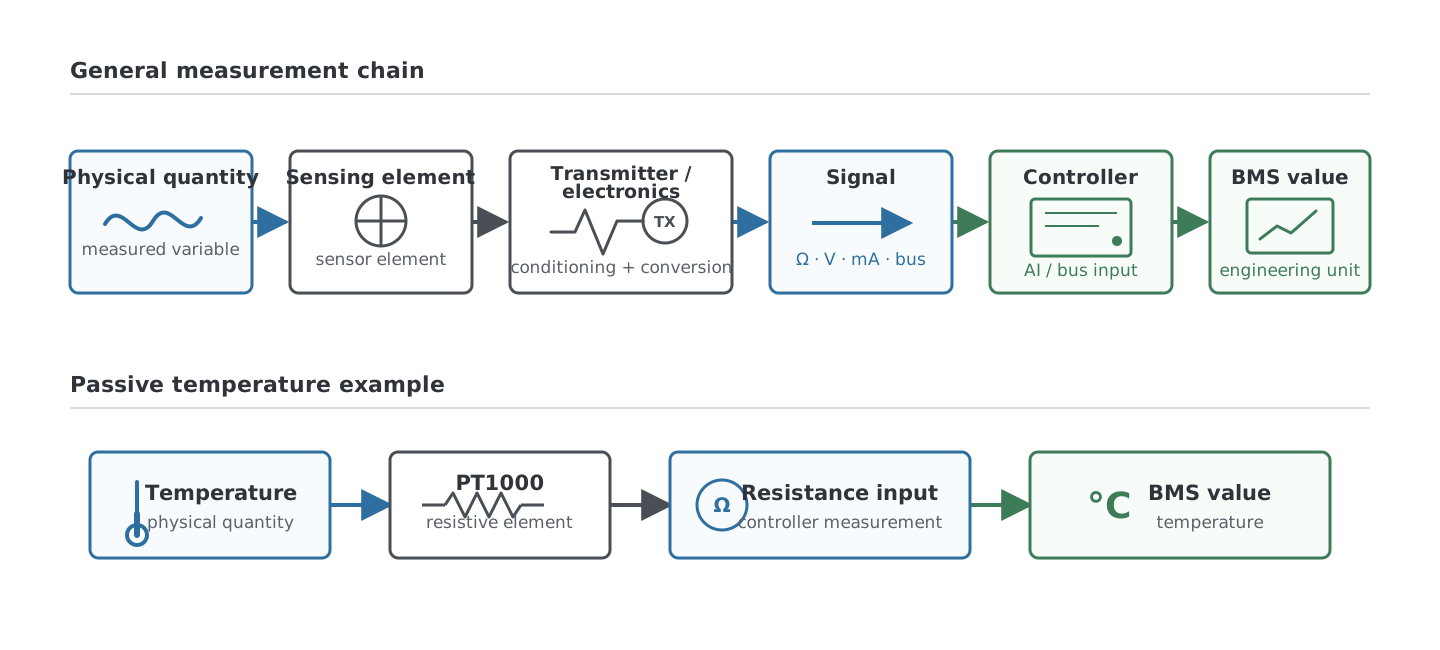
1. What is a sensor in building automation?
A sensor reacts to a physical quantity such as temperature, pressure, light, humidity or gas concentration. The sensing principle depends on what is being measured. A platinum resistance element changes electrical resistance with temperature, an NDIR CO₂ sensor measures the absorption of infrared light, a capacitive humidity sensor changes electrical characteristics as it absorbs water molecules, and a differential pressure sensor converts a pressure difference into an electrical response.
In everyday building automation language, the word sensor is often used for the complete field device. A wall-mounted CO₂ sensor may therefore contain the actual sensing element, a microcontroller, temperature compensation, calibration data, an analog output and a Modbus interface, yet everyone still calls the complete product a CO₂ sensor. This is normal terminology, but when troubleshooting it helps to separate the sensing element from the rest of the measurement chain.
A transmitter normally takes the output of a sensing element, processes it and transmits the result in a form that another device can use. Common transmitter outputs in building automation include 0–10 V, 2–10 V, 4–20 mA and digital communication such as Modbus or BACnet. Some temperature transmitters, for example, contain a PT100 or PT1000 element internally but send a standardized analog signal instead of exposing the resistance directly to the controller.
The exact terminology varies between manufacturers, so the product name alone does not tell you how the device is electrically connected. The wiring diagram and datasheet are the sources that matter.
2. Passive sensors and active transmitters
One of the most useful distinctions in building automation is between a passive resistive sensor and an active transmitter.
A passive temperature sensor such as a PT1000 or NTC does not normally calculate a temperature value and send it to the controller. Its electrical resistance changes with temperature. The controller measures that resistance and converts it to temperature using the configured resistance-to-temperature characteristic.
Room temperature
      ↓
PT1000 element
      ↓
Resistance in ohms
      ↓
Controller resistance input
      ↓
PT1000 conversion curve
      ↓
21.0 °C
An active transmitter performs more of the measurement inside the field device. A pressure transmitter, for example, measures the pressure with its internal sensing element, processes and compensates the measurement, and then converts the result into an output signal such as 0–10 V.
Duct pressure
      ↓
Pressure sensing element
      ↓
Signal processing and compensation
      ↓
0–10 V output
      ↓
Controller analog input
      ↓
Configured scaling
      ↓
185 Pa
This difference changes the troubleshooting process. With a passive sensor, measuring resistance at the controller terminals can often tell you a great deal about the sensor and wiring. With an active transmitter, measuring 5.0 V only proves that the transmitter is producing 5.0 V. It does not prove that the physical quantity represented by that voltage is correct.
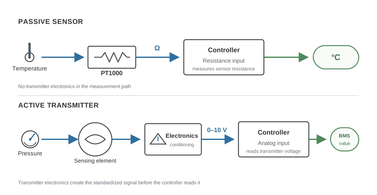
2.1 Passive does not mean completely unpowered measurement
A passive resistance sensor does not need a separate field power supply in the same way as a 24 V transmitter, but the controller still has to measure its resistance. The resistance input applies a small measuring current or voltage internally and determines the resistance from the resulting electrical response. The measuring current is intentionally small because excessive current would heat the sensing element and create self-heating error.
In normal building automation applications this is handled by the controller design, but it explains why a resistance input is not simply a passive continuity measurement. The input must specifically support the required sensor characteristic.
3. Resistive temperature sensors
Temperature is one of the few building automation measurements where a simple passive sensing element can often be connected directly to the controller. Common examples include PT100, PT1000, NTC10k, other NTC thermistors and manufacturer-specific nickel or thermistor curves.
The important point is that resistance by itself is not a temperature. The controller must know which sensor curve is connected. If a PT1000 is configured as an NTC sensor, or one NTC10k curve is configured as another NTC10k curve, the controller can receive a perfectly valid resistance measurement and still display the wrong temperature.
For unknown passive temperature sensors, the Temperature Sensor Identifier and Resistance Converter can compare measured resistance against supported PT100, PT1000, Ni1000 and NTC characteristics.
3.1 PT100 and PT1000
PT100 and PT1000 are platinum resistance temperature detectors, commonly abbreviated RTD. Their resistance increases as temperature increases, which means they have a positive temperature coefficient. The nominal resistance of a PT100 is 100 Ω at 0 °C, while the nominal resistance of a PT1000 is 1000 Ω at 0 °C. Their standardized resistance-to-temperature behavior is defined by IEC 60751.
Around normal building temperatures the PT1000 resistance changes by roughly 3.85 Ω per degree Celsius, while the PT100 changes by roughly 0.385 Ω per degree Celsius. For example, an IEC 60751 PT1000 is approximately 1078 Ω at 20 °C. The exact conversion is not perfectly linear over the full operating range, so controllers normally use the standardized characteristic rather than a simple fixed multiplier.
The higher resistance of the PT1000 makes resistance added by the field wiring less significant relative to the sensor itself. This is one reason PT1000 is convenient for two-wire temperature measurement in building automation. Pt100 measurements are more sensitive to lead-wire resistance, which is why higher-accuracy industrial Pt100 installations often use three-wire or four-wire compensation arrangements.
3.2 NTC thermistors
An NTC, or Negative Temperature Coefficient thermistor, behaves in the opposite direction: its resistance decreases as temperature increases. NTC thermistors are semiconductor devices and have a much larger resistance change per degree than platinum RTDs, but the relationship between resistance and temperature is strongly nonlinear.
A name such as NTC10k usually means that the thermistor has a nominal resistance of 10 kΩ at a specified reference temperature, commonly 25 °C. It does not define one universal NTC curve. Two different NTC10k sensors can both measure approximately 10 kΩ at 25 °C and produce noticeably different resistances at 0 °C, 10 °C or 50 °C because their material characteristics and curve coefficients are different.
This is a common field problem. An engineer measures around 10 kΩ at room temperature, configures the first NTC10k option available in the controller, and sees a believable value. The error may only become obvious when the outdoor temperature changes or the sensor is exposed to another part of its range. When the sensor type is uncertain, use manufacturer documentation or compare resistance at more than one known temperature.
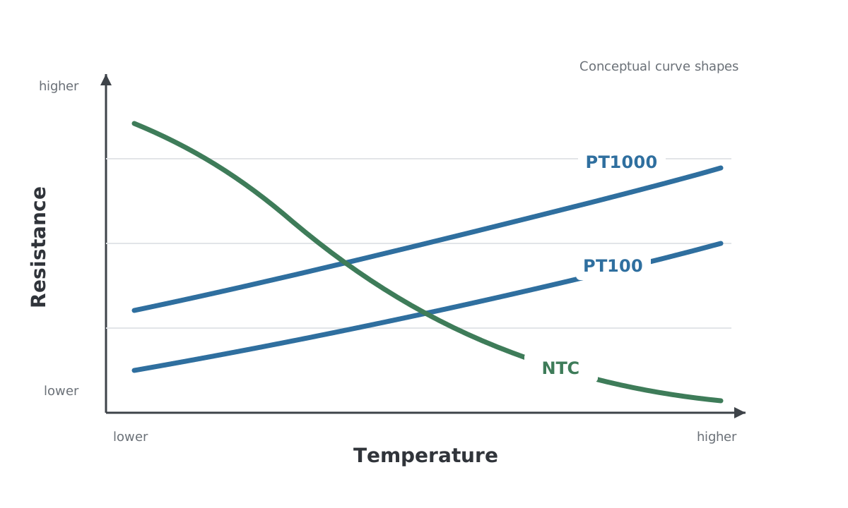
3.3 PT100 vs PT1000 vs NTC in practice
| Property | PT100 | PT1000 | NTC thermistor |
|---|---|---|---|
| Basic principle | Platinum RTD | Platinum RTD | Semiconductor thermistor |
| Nominal value | 100 Ω at 0 °C | 1000 Ω at 0 °C | Depends on type, often specified at 25 °C |
| Resistance with rising temperature | Increases | Increases | Decreases |
| Characteristic | Standardized IEC 60751 curve | Standardized IEC 60751 curve | Many different curves |
| Linearity | Relatively linear around HVAC temperatures | Relatively linear around HVAC temperatures | Strongly nonlinear |
| Lead resistance sensitivity in 2-wire connection | Higher | Lower | Depends on sensor resistance and wiring |
| Common field mistake | Lead resistance ignored | Wrong input type | Wrong NTC curve selected |
It is tempting to ask which of these sensors is simply “best”, but the useful question is whether the sensor is suitable for the controller input, required accuracy, cable length, installation and temperature range. In building automation all three can work very well when the controller is configured for the correct characteristic.
4. What is a transmitter actually transmitting?
A transmitter takes a measurement and converts it into a defined output. The controller does not necessarily know how the original physical quantity was measured. It only sees the final interface.
Consider a 0–500 Pa duct differential pressure transmitter with a 0–10 V output. Internally, the transmitter may contain a MEMS pressure sensing element, temperature compensation, calibration coefficients, analog-to-digital conversion and a microcontroller. The BMS controller sees none of this. It sees a voltage.
0 V  = 0 Pa
5 V  = 250 Pa
10 V = 500 Pa
If the controller receives 5.0 V and is configured for 0–500 Pa, it displays 250 Pa. If somebody accidentally configures the controller for 0–1000 Pa, exactly the same 5.0 V becomes 500 Pa. The pressure sensor is working, the analog input is working and the displayed value is still wrong.
This is why commissioning a transmitter requires checking both sides of the interface: what the transmitter is configured to send and what the controller is configured to interpret.
5. Common transmitter outputs
5.1 0–10 V
The 0–10 V signal is extremely common in building automation because it is simple to understand and easy to measure with a multimeter. A transmitter maps its measurement range to a voltage range. For example, a CO₂ transmitter configured for 0–2000 ppm may use:
0 V  = 0 ppm
10 V = 2000 ppm
If the measured signal is 4.2 V, the corresponding value is:
4.2 V / 10 V × 2000 ppm = 840 ppm
For a general 0–10 V signal starting from zero, the basic conversion is:
Engineering value = Voltage / 10 V × Full scale
Real devices may use other ranges such as 2–10 V or may allow the measurement range to be configured, so the actual datasheet and transmitter settings always take priority.
A voltage signal is referenced to a common electrical potential. Incorrect common wiring, ground potential differences, voltage drop in shared supply/common conductors, electrical noise or a failed transmitter supply can therefore affect the measurement. Long cable runs and electrically noisy environments deserve more attention than a short room-sensor cable in a clean installation.
For more detail on analog inputs, commons and scaling, see the I/O Guide: Digital and Analog Inputs and Outputs.
5.2 4–20 mA
A 4–20 mA current loop represents the measurement as current rather than voltage. A pressure transmitter configured for 0–1000 Pa could use:
4 mA  = 0 Pa
12 mA = 500 Pa
20 mA = 1000 Pa
The useful feature of 4–20 mA is the live zero. A valid zero measurement is represented by 4 mA rather than 0 mA. In a correctly designed and monitored loop, a current near zero can therefore indicate an open circuit, loss of power or another fault instead of being confused with a legitimate zero measurement. Some industrial transmitters also use defined under-range and over-range currents for diagnostics, but these details are product-specific.
Current loops are less directly affected by cable voltage drop than voltage-output transmitters as long as the transmitter still has enough compliance voltage to drive the required loop current. They are therefore widely used in industrial instrumentation and also appear in building automation, especially on pressure, flow and process-related measurements.
5.3 Digital communication
A sensor can also send its measurement digitally using a protocol such as Modbus RTU, Modbus TCP or BACnet. In that case there is no analog 0–10 V scaling between the sensor and controller, but the measurement chain has not disappeared. The sensor still contains a sensing element, calibration, compensation and internal conversion before placing a value into a register or object.
Digital communication also creates its own configuration questions. The controller may need the correct register address, data type, byte order, scaling factor and engineering unit. A register value of 812 might directly mean 812 ppm, or it could represent 81.2 ppm if a scale factor of 0.1 is specified. The fact that a value arrives digitally does not guarantee that it has been interpreted correctly.
For register interpretation and communication troubleshooting, see the Modbus RTU and TCP Guide.
Digital does not automatically mean more accurate. A digital sensor can report
21.37 °Cwhile the actual measurement accuracy is much lower than two decimal places. The number of displayed digits is not the same thing as measurement accuracy.
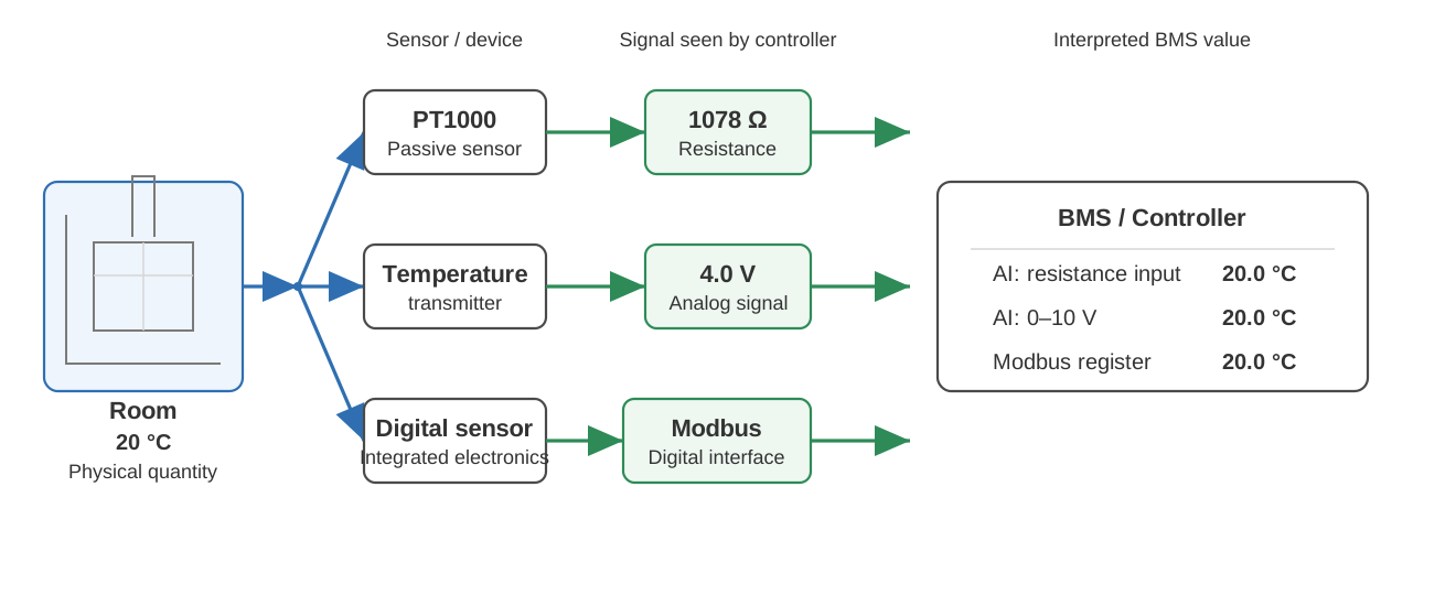
6. The same physical quantity can reach the BMS in different ways
Temperature is a good example because the same room temperature can be transmitted through several completely different electrical interfaces.
A passive PT1000 room sensor might produce approximately:
1078 Ω
An active temperature transmitter scaled from 0–50 °C might produce:
4.0 V = 20 °C
A digital room sensor might send:
Modbus register = 200
Scale = 0.1 °C
Value = 20.0 °C
All three devices measure temperature, but the controller inputs, wiring and troubleshooting methods are different. The correct question is therefore not only “What does this sensor measure?” but also “How does this device communicate the measurement to the controller?”
7. Temperature sensing in building automation
Temperature sensors are installed almost everywhere in an HVAC system: rooms, outdoor walls, supply and extract ducts, heating and cooling pipes, domestic hot water systems, heat exchangers, boilers and equipment cabinets. Passive PT1000 and NTC sensors are common because the sensing principle is simple and the controller can convert resistance directly into temperature. Active temperature transmitters are useful when a standardized analog output is preferred, when longer-distance instrumentation is required or when multiple measurements are combined in one device.
The sensing principle is only part of the measurement. Installation often introduces more error than the sensor specification. A wall sensor warmed by direct sunlight, electronics, a nearby radiator or air leaking through the cable conduit can report the temperature of its installation conditions rather than the representative room temperature. A duct probe installed too close to a heating coil, in a stratified section of duct or with insufficient insertion can also produce a technically valid but unrepresentative measurement.
For pipe temperature, the difference between a properly installed immersion sensor and a poorly attached surface sensor can be much larger than the difference between two good sensor elements. Thermal contact, insulation, response time and placement therefore need to be considered together with electrical accuracy.
8. Relative humidity sensors
Relative humidity is normally measured with an electronic sensor rather than a simple passive resistor connected directly to a controller. Capacitive polymer humidity sensors are widely used: the electrical capacitance of the sensing structure changes as water molecules interact with the humidity-sensitive material. Electronics inside the device convert that response into relative humidity, often with temperature compensation.
The complete field device may output 0–10 V, 4–20 mA, Modbus, BACnet or another digital signal. Combined room transmitters often measure temperature, relative humidity and CO₂ in the same enclosure even though each measurement uses a different sensing principle internally.
Humidity sensing is sensitive to the environment. Chemicals, volatile compounds, dust and other contaminants can affect the humidity-sensitive material and create temporary or permanent measurement shifts depending on the sensor design and exposure. Prolonged operation at extreme humidity can also affect some sensors. This is why a humidity transmitter that performs well in a normal office should not automatically be assumed to behave the same way in a swimming pool, industrial process, kitchen exhaust environment or chemically contaminated space.
When humidity accuracy matters, compare the measurement against a suitable reference under stable conditions. Simply verifying that the transmitter outputs the expected voltage for the displayed humidity only proves that the output stage and scaling agree with the transmitter’s own measurement.
9. CO₂ sensors
Carbon dioxide is one of the most important air-quality-related measurements in building automation because it is widely used for demand-controlled ventilation. In normally occupied spaces, indoor CO₂ concentration is strongly affected by people and ventilation, so it can be used as an indicator for adjusting outdoor-air ventilation demand. It should not, however, be treated as a complete measurement of indoor air quality because pollutants from materials, cleaning products, cooking, processes or other sources may not follow CO₂ concentration.
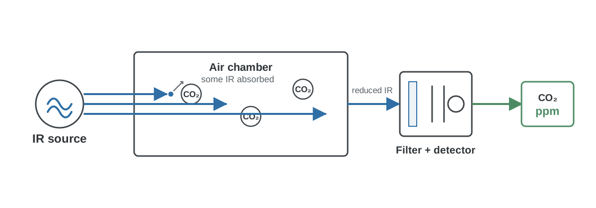
Many building automation CO₂ sensors use non-dispersive infrared, or NDIR, measurement. CO₂ absorbs infrared radiation at characteristic wavelengths. An NDIR sensor sends infrared light through a measurement path containing the air sample and detects how strongly light in the relevant wavelength region is absorbed. The electronics then calculate CO₂ concentration from the measured optical response while compensating for factors defined by the sensor design.
9.1 Why CO₂ sensors can drift
An NDIR CO₂ transmitter contains much more than a passive temperature resistor. The optical source, detector, measurement chamber, contamination, electronic compensation and calibration can all influence long-term behavior. Good sensor designs use techniques such as reference measurements, internal compensation and calibration algorithms to maintain stability, but the implementation differs between products.
Some CO₂ sensors use automatic baseline or background correction. A common approach is to observe the lowest CO₂ measurement over a longer period and assume that the space periodically returns to a known background concentration. This can work well in spaces that regularly become unoccupied and are flushed with outdoor air. It can produce problems if the algorithm’s assumption is not true, for example in continuously occupied spaces where CO₂ never reaches the expected background level. The exact behavior and suitability of automatic correction must therefore be checked from the sensor documentation rather than assumed from the term “NDIR” alone.
Other CO₂ sensor designs use optical reference channels or other methods to compensate for source aging and contamination without relying on the room periodically reaching a specific background concentration. This is a good example of why two devices using the same basic NDIR principle can have very different long-term specifications.
9.2 CO₂ transmitter scaling
A common analog CO₂ transmitter range is 0–2000 ppm mapped to 0–10 V, although many other ranges are available. If the transmitter is changed from 0–2000 ppm to 0–5000 ppm but the controller scaling remains unchanged, the BMS value will be wrong even though both devices are functioning normally.
During commissioning, record the configured range together with the BMS point configuration. If the device has a display, compare the local reading, raw analog signal and BMS value. This quickly separates a sensing problem from a signal-scaling problem.
10. Carbon monoxide sensors
Carbon monoxide, or CO, is very different from CO₂. CO is a toxic gas, and CO detection in applications such as parking garages can be part of a safety-related ventilation or alarm function. The sensor selection, placement, testing and replacement requirements should therefore follow the applicable project requirements, local regulations and manufacturer instructions rather than ordinary comfort-control practices.
Many CO detectors use an electrochemical sensing cell. Gas reaches the cell and participates in an electrochemical reaction that produces an electrical signal related to concentration. Unlike a passive platinum temperature sensor, an electrochemical gas cell has a finite rated operating life. Its sensitivity can change with age and exposure, and manufacturers specify replacement, calibration or end-of-life requirements for the actual product. Some commercial electrochemical CO cells are specified for only a few years of operation, while other detector designs may have different service intervals, so one universal lifetime should not be applied to every CO sensor.
Electrochemical gas sensors can also respond to gases other than their intended target to some degree. Manufacturers therefore specify cross-sensitivities and environmental limits. A sensor that still produces a believable ppm value is not automatically proven healthy merely because the BMS trend looks reasonable.
For a safety-relevant CO installation, functional testing with the appropriate method and adherence to the manufacturer’s end-of-life requirements are much more important than trying to infer sensor condition from BMS trends alone.
11. VOC sensors
VOC means volatile organic compounds. This is a broad group of chemicals rather than one specific gas. That distinction matters because a typical building automation VOC sensor does not behave like a CO₂ sensor that measures one defined molecule at a characteristic infrared absorption band.
Many indoor-air-quality VOC sensors use a heated metal-oxide semiconductor, often abbreviated MOS or MOX. The electrical resistance of the sensing material changes when it interacts with reducing or oxidizing gases. The sensor can respond to many different VOCs, and the strength of the response depends on the compound, concentration, humidity, temperature, sensor material and signal-processing algorithm.
For this reason, VOC outputs require careful interpretation. One manufacturer may provide a unitless VOC index, another may provide a value expressed as an equivalent concentration, and another may simply provide an air-quality level. These values are not automatically interchangeable. A displayed value of 500 from a VOC sensor does not mean the same thing as 500 ppm of CO₂, and it may not mean 500 ppm of any specific VOC at all.
Some modern VOC algorithms intentionally adapt to the recent background level and emphasize changes in indoor air quality. This is useful for ventilation control because the sensor can react to events such as cleaning products, cooking, occupants or material emissions, but the result should be understood as an air-quality signal rather than laboratory identification of individual gases.
VOC, eCO₂ and measured CO₂ are not the same thing. Some devices calculate an “equivalent CO₂” value from a broad gas sensor. That number is an algorithmic estimate and should not be treated as a direct NDIR CO₂ measurement.
11.1 VOC sensor aging and contamination
Heated metal-oxide sensors are designed for long operation, but their response can still be influenced by contamination, poisoning compounds, temperature, humidity and long-term changes in the sensing surface. Product-specific algorithms may compensate for part of this behavior. The result is that VOC troubleshooting should focus on the actual output definition and expected behavior of the product, not only on whether the sensor returns a number.
If a VOC value appears permanently high or low, check the device’s warm-up and conditioning requirements, recent exposure to cleaning chemicals or solvents, humidity conditions, ventilation pattern and any baseline or index algorithm described by the manufacturer.
12. Pressure and differential pressure sensors
Pressure sensing is central to HVAC control. Building automation commonly measures supply and extract duct pressure, room pressure, filter pressure drop, fan pressure and differential pressure across equipment. Many of these measurements involve differences of only tens or hundreds of pascals, which makes installation and zero stability important.
A differential pressure transmitter has a high-pressure and a low-pressure connection. The measured value is the difference between them:
Δp = p(high) - p(low)
For a filter, one pressure connection is installed before the filter and the other after it. As the filter becomes loaded, the pressure drop normally increases. For duct static-pressure control, the pressure connection arrangement and measurement point depend on the application.
12.1 Zero matters
If both differential-pressure ports are exposed to the same stable pressure, the expected differential pressure is approximately zero. If the transmitter reports a significant offset, possible causes include zero drift, mounting orientation, temperature effects, tubing problems or a need for zero calibration. Some HVAC pressure transmitters provide manual zeroing, while others use automatic zero functions.
Mounting orientation can matter because the sensing element itself is affected by gravity and mechanical stress. Some manufacturers explicitly instruct the installer to perform a zero adjustment when the sensor is mounted in a different orientation. This is why a pressure transmitter should not automatically be replaced just because it shows 15 Pa with the tubes disconnected; first follow the product’s zeroing procedure and installation instructions.
12.2 Range selection matters
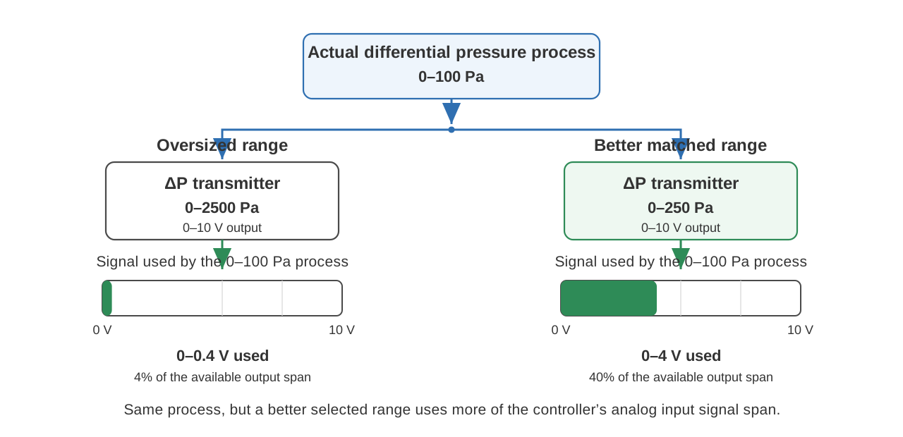
Choosing a transmitter range that is much wider than the actual measurement reduces the useful signal span. Suppose a 0–2500 Pa transmitter uses 0–10 V but the real duct pressure varies only between 0 and 100 Pa. The entire useful control range then occupies only 0–0.4 V. Noise, analog input error and small offsets become much more important relative to the useful signal.
Select a range that safely covers the expected operating conditions without being unnecessarily wide. Many modern transmitters have selectable ranges, but changing that range also means checking the BMS scaling.
13. Other sensors used in building automation
Building automation uses many sensing principles beyond temperature, humidity, gas concentration and pressure. The same basic engineering questions still apply: what physical quantity is measured, how does the sensing element respond, how is the result transmitted, and what can cause the measurement to be wrong?
13.1 Occupancy and presence sensors
A PIR sensor detects changes in infrared radiation caused by moving warm objects. It is very useful for detecting motion but does not directly count people and may stop detecting a person who remains sufficiently still. Microwave or radar-based presence sensors use radio-frequency reflections and can detect different kinds of motion. Multi-technology devices combine sensing methods to improve presence detection.
For control design, distinguish between motion detected, presence estimated and people counted. These are not equivalent measurements, even if all three may ultimately be used to influence ventilation, lighting or room mode.
13.2 Particulate matter sensors
Many PM2.5 and PM10 sensors use optical light scattering. Air passes through an optical measurement region, particles scatter light, and the device estimates particle concentration from the detected scattering. The conversion from optical response to a mass concentration depends on assumptions about particle size, optical properties and calibration, so an inexpensive optical PM sensor is not the same thing as a laboratory reference instrument.
Dust accumulation in the optical path, airflow changes and aerosol type can affect long-term results. The maintenance instructions of the complete device matter more than the fact that the output happens to be expressed in µg/m³.
13.3 Light sensors
Illuminance sensors typically report light level in lux. Their spectral response and installation orientation influence how well the reading represents the light perceived in the controlled space. A sensor mounted in direct sunlight or facing a luminaire may not represent the useful working-plane illumination that the control sequence is intended to maintain.
13.4 Flow measurement
Air and water flow can be measured through several principles. HVAC airflow may be inferred from differential pressure across a known measurement device, while water flow meters may use ultrasonic, electromagnetic, mechanical or thermal principles. When the BMS receives a flow value, understand whether the device measures flow directly or calculates it from another measurement such as differential pressure.
14. A sensor can be electrically correct and physically wrong
This is one of the most important troubleshooting principles in building automation.
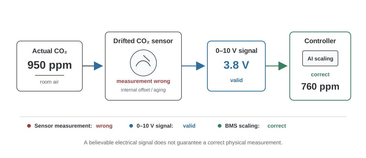
Imagine a CO₂ transmitter configured for 0–2000 ppm and 0–10 V. The BMS receives 3.8 V and correctly scales it to 760 ppm. A multimeter confirms 3.8 V at the controller terminals. The analog input, wiring and scaling are therefore behaving exactly as expected.
But suppose a calibrated reference instrument in the same location measures 950 ppm.
Actual/reference CO₂:   950 ppm
Transmitter measurement: 760 ppm
Analog output:             3.8 V
BMS calculation:           760 ppm
The electrical signal is correct for the transmitter’s own measurement, but the transmitter measurement is wrong. Measuring the voltage alone cannot detect this.
The same principle applies to humidity, pressure, VOC, CO and active temperature transmitters. The BMS can only display the information it receives. A sensor that has drifted does not necessarily produce a communication alarm or an impossible electrical value.
15. Where measurement error comes from
The displayed BMS value is the result of an entire measurement chain. Looking only at the sensor datasheet can therefore give a false sense of accuracy.
A typical active measurement may contain:
Physical quantity
      ↓
Sensing element
      ↓
Mechanical installation
      ↓
Sensor electronics
      ↓
Temperature / humidity compensation
      ↓
Calibration coefficients
      ↓
Analog or digital output
      ↓
Field wiring / communication
      ↓
Controller input
      ↓
Scaling and engineering units
      ↓
BMS value
Possible errors include incorrect sensor placement, sensor drift, contamination, cable resistance, ground offsets, analog input error, wrong signal range, wrong sensor curve, incorrect Modbus scaling or a simple unit mistake. Several small errors can also exist at the same time.
For passive sensors the chain is shorter, but not error-free:
Temperature
      ↓
Sensor element
      ↓
Thermal installation
      ↓
Cable resistance / connections
      ↓
Controller resistance measurement
      ↓
Selected sensor curve
      ↓
BMS temperature
A good troubleshooting process moves through this chain systematically instead of replacing components at random.
16. Sensor placement can matter more than sensor accuracy
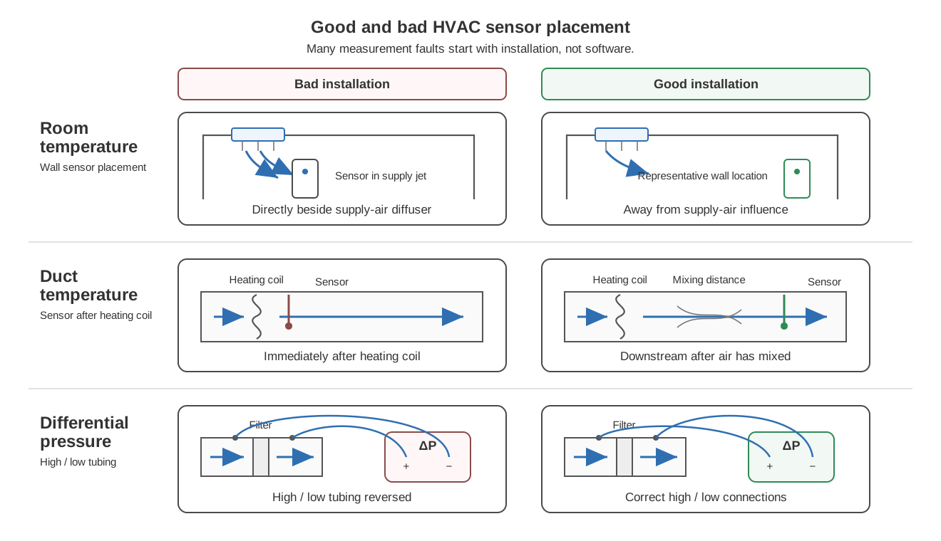
A sensor can be perfectly calibrated and still measure the wrong thing because it is installed in the wrong location. This is particularly common in HVAC systems, where air temperature, pressure, humidity and contaminant concentration can vary significantly over short distances.
A room temperature sensor installed in direct sunlight may read several degrees higher than representative room air. A sensor above warm electronics can be affected by self-heating from the installation. Air flowing through a wall cavity or cable conduit can influence a wall-mounted sensor from behind. A CO₂ sensor directly beside a supply-air diffuser may see cleaner air than the occupied zone, while one installed in a stagnant corner may respond slowly to changing occupancy.
Duct sensors have similar problems. A temperature probe positioned immediately after a heating coil may be exposed to incomplete air mixing. A humidity probe can be affected by condensation. A pressure pickup located in turbulent airflow may produce an unstable reading. Differential-pressure tubing can be kinked, leaking, filled with condensation or connected to the wrong ports.
The first question should therefore sometimes be “Is this sensor measuring a representative location?” rather than “Is this sensor accurate?”
17. Accuracy, resolution, repeatability and drift
These terms are often mixed together even though they describe different properties of a measurement.
Accuracy describes how close a measurement is to the value being measured. Repeatability describes how closely repeated measurements agree when conditions remain the same. Resolution describes the smallest change the measurement system can display or distinguish. Drift describes how the measurement changes over time even when the measured condition has not changed correspondingly.
A BMS may display temperature as:
21.37 °C
The two decimal places only tell you something about display or numerical resolution. They do not prove that the room temperature is known within ±0.01 °C. The sensor might have an accuracy specification of several tenths of a degree, and installation effects may add further uncertainty.
A sensor can also be highly repeatable but inaccurate. If the actual temperature is stable at 21.0 °C and the sensor repeatedly reports 21.5 °C, the measurement is consistent but offset.
Reference: 21.0 °C

Sensor readings:
21.5 °C
21.5 °C
21.5 °C
21.5 °C
That is useful information during troubleshooting because a stable offset can point toward calibration, installation or sensor-curve problems, while an unstable value may indicate noise, intermittent wiring, airflow variation or a failing device.
18. How different sensors age
Sensors do not all age in the same way. A passive platinum RTD, an NTC thermistor, a polymer humidity sensor, an NDIR CO₂ sensor, an electrochemical CO cell and a heated MOS VOC sensor are physically different technologies. It would be misleading to give them one common service-life rule.
An active transmitter also has more than the sensing element to consider. Voltage references, analog-to-digital conversion, compensation data, output electronics, power supplies and internal connections are all part of the complete measurement device. A transmitter can continue to send a perfectly valid voltage or digital value while its sensing element has drifted, and the opposite is also possible: the sensing element can be healthy while the output circuit, supply or wiring introduces the error.
18.1 PT100 and PT1000
Platinum RTDs are valued for reproducibility and long-term stability. In normal building applications the field problem is often not dramatic aging of the platinum element itself, but the complete installation: damaged probes, moisture ingress, corrosion, poor terminals, increased lead resistance, mechanical stress or a sensor installed in the wrong place. High-accuracy applications can still require calibration because stable does not mean perfectly unchanged forever.
18.2 NTC thermistors
NTC thermistors can also provide long and stable service when operated within their specified conditions. Their larger practical risk in building automation is often identification and curve mismatch. However, thermistors can change with prolonged thermal stress, moisture or harsh environmental exposure, and the manufacturer’s stability specifications should be considered when accuracy is important.
18.3 Humidity sensors
Humidity-sensitive materials interact directly with the surrounding air. Contaminants such as solvents and other volatile compounds can enter the sensing layer and change its electrical behavior. Depending on the sensor and contaminant, the resulting shift may be reversible after recovery or may create longer-term drift. High humidity, condensation and chemical exposure deserve particular attention.
18.4 CO₂ sensors
NDIR CO₂ sensors can be very stable, but optical sources, detectors and surfaces can change with age or contamination. Good designs use internal references and compensation to reduce these effects. Other designs rely partly on periodic baseline correction. The correct maintenance strategy therefore depends strongly on the actual sensor architecture and manufacturer specification.
18.5 CO sensors
Electrochemical CO sensing cells have a finite operating life and should be treated as components that eventually require replacement. Sensitivity, electrolyte condition and electrode performance change with time and environmental exposure. Safety-related detectors may include an end-of-life indication, and that requirement must not be bypassed simply because the BMS is still receiving a plausible analog value.
18.6 VOC sensors
MOS VOC sensors contain heated sensing material whose response is affected by surface chemistry. Modern sensors and algorithms can provide long service life, but contamination, poisoning substances, humidity and changes in baseline can influence behavior. Because many outputs are relative or algorithmic indexes, understanding how the specific product adapts over time is essential when interpreting trends.
18.7 Pressure sensors
Differential pressure sensors can develop zero offset over time, and their zero can also be influenced by temperature and mounting orientation. Many HVAC products therefore provide manual or automatic zeroing. Tubing and pressure pickups may age or become contaminated even when the electronic sensing element remains healthy.
| Sensor type | Common long-term concern |
|---|---|
| PT100 / PT1000 | Wiring, connections, moisture, mechanical damage, calibration in high-accuracy applications |
| NTC | Wrong curve, thermal/environmental aging, moisture |
| Relative humidity | Contamination, chemical exposure, prolonged extreme humidity |
| CO₂ | Optical aging/contamination, calibration strategy, baseline assumptions |
| CO | Finite electrochemical cell life, sensitivity change, cross-sensitivity |
| VOC | Baseline behavior, contamination, poisoning, algorithm interpretation |
| Differential pressure | Zero offset, mounting effect, tubing and pressure pickup condition |
19. Calibration is not the same as checking the electrical output
A multimeter is one of the best troubleshooting tools in building automation, but it is important to understand what it proves.
If a 0–10 V humidity transmitter displays 45 %RH and produces 4.5 V for a configured 0–100 %RH range, a multimeter can confirm that the output stage, wiring and controller scaling are consistent. It does not confirm that the air is actually at 45 %RH. For that, the sensor measurement must be compared with a suitable humidity reference.
Similarly, measuring 12 mA from a 0–1000 Pa pressure transmitter proves that the transmitter is sending a signal corresponding to 500 Pa. To verify the pressure measurement itself, apply or compare against a known pressure reference.
Strictly speaking, calibration means comparing a measurement instrument with a suitable reference and determining the relationship or error. Adjustment changes the instrument so that its indication is corrected. Many field devices use the word “calibration” for a menu function that actually performs an adjustment, so it is worth reading the procedure carefully.
20. A practical sensor troubleshooting method
When a measurement looks wrong, work from the physical process toward the controller. This is usually faster than changing software settings first and hoping the value improves.
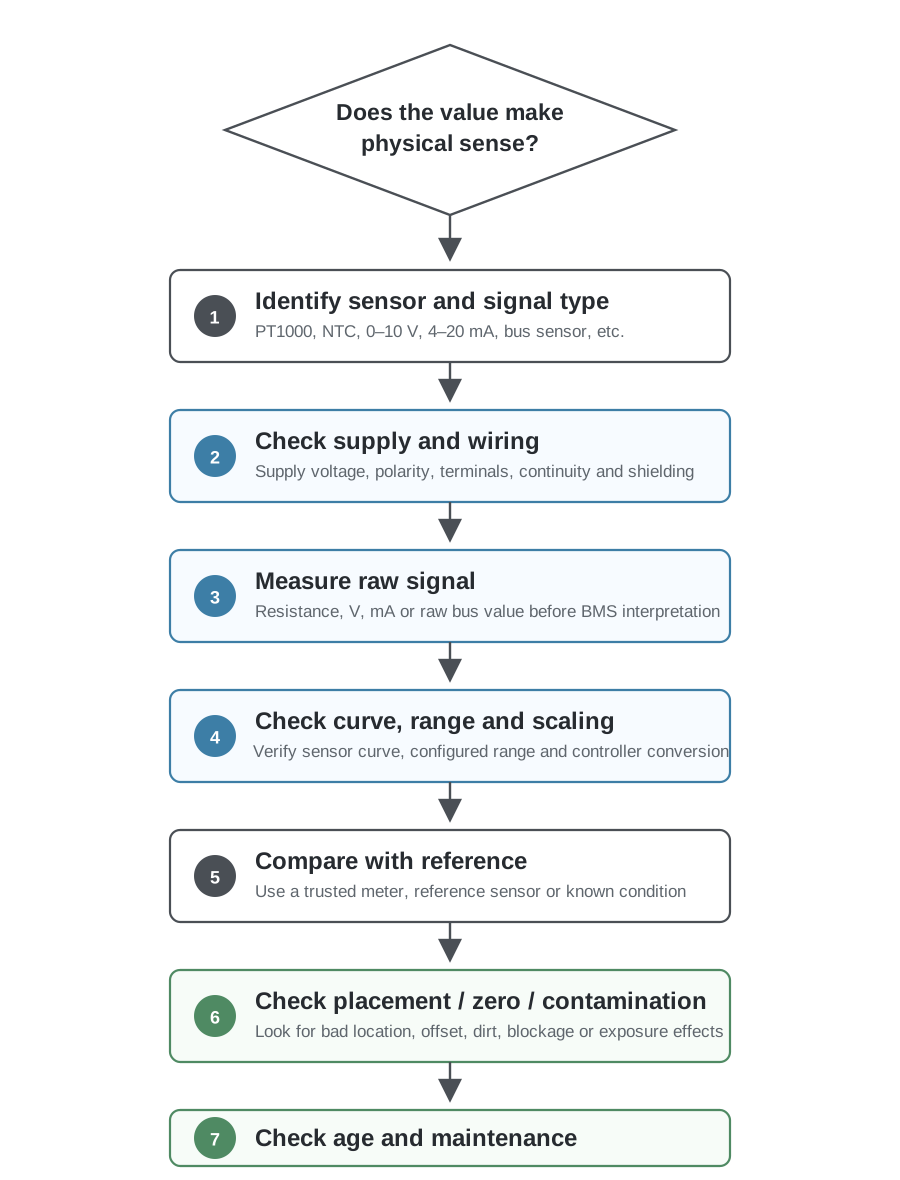
20.1 Step 1: Does the value make physical sense?
Start with the process. A room temperature of 42 °C in an occupied office is suspicious. A supply duct pressure of exactly 0 Pa while the fan is running is suspicious. A CO₂ value that never changes between an empty night and a crowded meeting is suspicious.
At the same time, avoid assuming that a surprising value must be an electrical fault. A dirty filter can genuinely create high differential pressure, a failed heating valve can produce an abnormal temperature, and a poorly ventilated room can genuinely have elevated CO₂.
20.2 Step 2: Identify the actual sensor and signal type
Before measuring anything, determine what is connected.
Is it:
- PT100?
- PT1000?
- NTC10k?
- another thermistor curve?
- 0–10 V?
- 2–10 V?
- 4–20 mA?
- Modbus?
- BACnet?
Do not assume from the BMS point name. Check the sensor label, wiring diagram, controller configuration and product documentation.
20.3 Step 3: Check supply and wiring
Active transmitters need the correct supply voltage. Check the supply at the field device under operating conditions, not only at the panel. Verify common connections, polarity where applicable, terminal assignments and cable condition.
For passive resistance sensors, isolate the sensor appropriately before measuring resistance so that the controller’s measuring circuit does not affect the multimeter reading. Check for open circuit, short circuit and unexpected resistance added by damaged or corroded connections.
20.4 Step 4: Measure the raw signal
Measure what the controller actually receives.
PT1000 / NTC  → Ω
0–10 V        → V
4–20 mA       → mA
Digital       → raw register/object and communication diagnostics
The raw signal divides the problem in half. If the physical sensor output is correct but the BMS value is wrong, focus on the controller input, conversion, scaling or protocol interpretation. If the raw signal is already wrong, focus on the transmitter, sensor, wiring or physical process.
20.5 Step 5: Convert the raw signal independently
Do not rely only on the BMS display. Calculate what the raw signal should mean.
Example:
Transmitter range: 0–2000 ppm CO₂
Output:            0–10 V
Measured:          5.0 V

Expected value:
5.0 / 10 × 2000 = 1000 ppm
If the BMS shows 500 ppm, the scaling is wrong. If the BMS shows approximately 1000 ppm, the controller and scaling are likely correct and the next question is whether the transmitter’s 1000 ppm measurement is physically correct.
20.6 Step 6: Check the configured curve, range and units
Many measurement errors are configuration errors.
Typical examples include:
- NTC10k curve A connected but NTC10k curve B selected
- PT1000 connected but Ni1000 selected
- transmitter configured 0–500 Pa while BMS expects 0–1000 Pa
- transmitter changed from 0–2000 ppm to 0–5000 ppm without changing BMS scaling
- Modbus value uses a 0.1 scale factor but BMS treats it as an integer engineering value
- pressure shown in kPa while point configuration assumes Pa
Configuration errors are dangerous because the resulting values often look believable.
20.7 Step 7: Compare the physical measurement with a reference
If the electrical chain is correct, compare the sensor against a suitable reference. Put the reference as close as reasonably possible to the measurement location and allow both instruments to stabilize. For room measurements, remember that gradients and airflow can make two nearby locations genuinely different.
A reference instrument should itself be suitable for the required accuracy. Comparing two unknown sensors and choosing the value that “looks right” is not calibration.
20.8 Step 8: Check installation and environmental effects
Inspect sensor placement, airflow, thermal contact, tubing, condensation, contamination and nearby heat sources. For CO₂ and VOC devices, consider whether the ventilation pattern and sensor algorithm can influence baseline behavior. For pressure transmitters, check zero and tubing before replacing electronics.
20.9 Step 9: Check age and maintenance requirements
Finally, check the sensor’s commissioning date and manufacturer requirements. An electrochemical gas detector at the end of its rated sensor life should not remain in service merely because its output still looks reasonable. Similarly, a humidity or CO₂ transmitter that has operated for years in a harsh environment may deserve verification even if it has not generated a fault code.
21. Selecting a sensor for a building automation project
A good sensor selection starts from the control function, not from a preferred signal type. First define what needs to be measured and how accurately it needs to be known. A room-temperature control loop, a filter alarm and a carbon monoxide safety function have very different requirements even though all three eventually appear as BMS points.
21.1 Measurement range
Choose a range that covers normal operation and credible abnormal conditions without being unnecessarily wide. A 0–7000 Pa pressure transmitter can technically measure a 100 Pa duct-pressure process, but a more appropriate range usually gives a much more useful signal. The same reasoning applies to CO₂, humidity and other transmitters with selectable ranges.
21.2 Accuracy and stability
Read the complete accuracy specification. Determine whether it applies across the required temperature range and whether long-term drift is specified separately. A very good factory accuracy is less useful if the sensor drifts significantly before the next planned maintenance interval.
21.3 Signal and controller compatibility
Check whether the controller supports the required resistance curve, voltage signal, current loop or communication protocol. For analog transmitters, confirm the electrical input range and common arrangement. For digital devices, confirm the protocol profile, available objects/registers and required configuration.
21.4 Power supply
Passive resistance sensors do not require a separate field supply, while active transmitters may require 24 VAC, 24 VDC or another supply. Some 4–20 mA devices are two-wire loop-powered, while others have separate power and output terminals. Never infer the wiring from the signal name alone.
21.5 Environment and installation
Check temperature, humidity, condensation, ingress protection, chemical exposure and mounting requirements. A normal room sensor and a sensor installed in a parking garage, swimming pool, outdoor air intake or industrial kitchen are exposed to very different conditions.
21.6 Maintenance
Consider how the measurement will be verified after commissioning. Can the sensor be checked in the field? Does it require gas calibration? Does it have a replaceable sensing module? Does it provide an end-of-life indication? Can pressure zero be adjusted without disconnecting the whole installation?
The cheapest sensor at installation is not necessarily the cheapest measurement over the life of the building if it is difficult to verify, replace or recalibrate.
22. Resistive sensor or transmitter?
For temperature measurement, the choice between a passive resistive sensor and an active transmitter is often practical rather than philosophical.
A passive PT1000 or NTC sensor is attractive when the controller already supports the correct characteristic and the cable length and environment are suitable. The field device is simple, no separate transmitter supply is needed, and troubleshooting with a resistance measurement is straightforward. The same sensor cannot, however, be used for measurements such as CO₂ or relative humidity because those quantities require a more complex sensing principle and electronics.
An active transmitter makes sense when the sensing technology already requires electronics, when a standardized analog signal is preferred, when local compensation or processing is required, or when the measurement must be communicated digitally. The tradeoff is a longer measurement chain: there are more configuration parameters and more components that can influence the final value.
| Question | Passive resistive sensor | Active transmitter |
|---|---|---|
| Typical quantities | Mainly temperature | Temperature, pressure, humidity, CO₂, CO, VOC, flow and many others |
| Separate field power | Usually no | Usually yes, except loop-powered arrangements use the signal loop |
| Controller sees | Resistance | Voltage, current or digital value |
| Conversion to engineering value | Mainly in controller | Partly or mostly in transmitter |
| Easy raw check | Resistance measurement | Voltage/current/register measurement |
| Can raw electrical check prove physical accuracy? | Sometimes strongly supports it if curve and installation are known | No, it mainly verifies the output side |
| Common configuration issue | Wrong sensor curve | Wrong range or scaling |
23. What should be documented?
Good sensor documentation makes future troubleshooting much easier. A BMS point name such as TE01 or CO2_ROOM_12 is not enough to explain how the measurement works.
For important measurements, document at least:
- measured quantity and engineering unit
- sensor/transmitter manufacturer and model
- sensing principle where relevant
- passive sensor characteristic, such as PT1000 or exact NTC curve
- transmitter output, such as 0–10 V or 4–20 mA
- configured transmitter measurement range
- controller input type and scaling
- digital register/object details where applicable
- installation location
- commissioning or calibration date where relevant
- planned maintenance or replacement requirements for life-limited sensors
This information allows the next engineer to start troubleshooting from facts instead of reverse-engineering the installation from a voltage reading and a point name.
24. Practical examples
24.1 PT1000 room temperature is wrong
The BMS shows 5 °C in a room that is clearly close to 20 °C. The sensor resistance measured after appropriate isolation is approximately 1078 Ω. That resistance is consistent with a PT1000 near 20 °C, so the sensing element and cable are unlikely to explain a 5 °C indication.
The next checks should be the configured sensor type and controller input. If the input is configured for another resistance characteristic, the controller can measure 1078 Ω correctly and still calculate the wrong temperature.
24.2 CO₂ value is exactly half of the expected value
A room CO₂ transmitter displays 1000 ppm locally. Its analog output measures 5.0 V. The transmitter is configured for 0–2000 ppm, so 5.0 V correctly represents 1000 ppm. The BMS displays 500 ppm.
The field device and wiring are behaving correctly. The BMS input is probably scaled for 0–1000 ppm instead of 0–2000 ppm.
24.3 Pressure transmitter reads 22 Pa with both tubes removed
Both pressure ports are open to the same room, but the differential-pressure transmitter shows 22 Pa. Before replacing the sensor, check its mounting orientation and perform the manufacturer’s zero-calibration procedure. Also make sure there is no residual pressure in connected tubing if the test is performed with tubes attached.
If the transmitter returns close to zero after the specified procedure, the original issue was zero offset rather than a failed pressure sensor.
24.4 Humidity signal and BMS scaling are correct, but the measurement is still wrong
A 0–10 V humidity transmitter is configured for 0–100 %RH. It outputs 6.0 V, and the BMS correctly displays 60 %RH. A trusted reference instrument located beside the transmitter stabilizes at 48 %RH.
There is no reason to change the BMS scaling. The problem is upstream of the analog output: sensor drift, contamination, installation or transmitter calibration should be investigated.
24.5 VOC value stays high after cleaning
A room VOC sensor rises sharply during cleaning and remains elevated long after the room appears normal. This may be a genuine response to residual volatile compounds, but the behavior also depends on the sensing element and algorithm. Review the manufacturer’s recovery, conditioning and baseline behavior before assuming that a fixed numeric threshold represents a specific gas concentration.
25. Key principles to remember
The most useful way to understand sensing in building automation is to follow the complete path from the physical world to the BMS value.
A PT1000 does not send temperature; it changes resistance. A 0–10 V pressure transmitter does not send pressure directly; it sends voltage that represents a configured pressure range. A Modbus CO₂ sensor may send a digital number, but the physical measurement can still drift. A VOC sensor may output an air-quality index that should not be interpreted as the concentration of one specific gas.
When a value is wrong, separate the problem into layers:
- Is the physical process and sensor location representative?
- Is the sensing element measuring correctly?
- Is the transmitter converting the measurement correctly?
- Is the signal reaching the controller correctly?
- Is the controller using the correct curve, range, scaling and units?
- Has the sensor drifted, become contaminated or reached a maintenance limit?
This approach works across temperature, pressure, humidity, CO₂, CO, VOC and many other building automation measurements. Instead of treating every strange value as a controller problem or every old sensor as automatically defective, you can identify which part of the measurement chain is actually responsible.
Related LumiBMS guides and tools
- I/O Guide: Digital and Analog Inputs and Outputs
- Temperature Sensor Identifier and Resistance Converter
- Modbus RTU and TCP Guide
- Interactive AHU Simulator
Technical references
The principles in this guide are based on established sensor technology and manufacturer documentation. Useful primary references include:
- IEC 60751 — Industrial platinum resistance thermometers and platinum temperature sensors.
- WIKA — Pt100/Pt1000 resistance thermometers — Pt100/Pt1000 nominal resistance, IEC 60751 characteristics and lead-resistance considerations.
- TDK Electronics — NTC thermistors, general technical information — NTC operating principle and resistance/temperature behavior.
- Vaisala — NDIR CO₂ measurement principle — Infrared absorption, optical reference measurement and compensation.
- Vaisala — HVAC CO₂ measurement stability — Long-term NDIR considerations and limitations of background-calibration assumptions.
- Senseair — NDIR technology — NDIR principles and an example of automatic baseline correction.
- Sensirion — SGP40 VOC sensor datasheet — Metal-oxide VOC sensing and VOC Index processing.
- Sensirion — Humidity sensor contamination guide — Contamination mechanisms in humidity sensors.
- Honeywell / RAE Systems — Electrochemical sensors for toxic gases — CO sensor operating-life and cross-sensitivity examples.
- Siemens — HVAC differential-pressure sensor commissioning — Mounting effects and zero-calibration guidance.
- NIST — Bias, precision, accuracy and resolution — Measurement terminology used in Section 17.